How to Use R-XSR Receiver: Examples, Pinouts, and Specs
Introduction
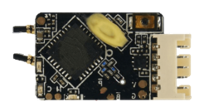
The FrSky R-XSR Receiver is a lightweight and compact receiver designed for remote control applications, particularly in drones and model aircraft. It is a full-range receiver that supports telemetry, allowing users to monitor critical flight data in real time. The R-XSR is compatible with FrSky transmitters using the ACCST (Advanced Continuous Channel Shifting Technology) protocol, making it a popular choice for hobbyists and professionals alike.
Explore Projects Built with R-XSR Receiver


Explore Projects Built with R-XSR Receiver
Common Applications and Use Cases
- Remote-controlled drones and quadcopters
- Fixed-wing model aircraft
- FPV (First-Person View) racing drones
- Applications requiring telemetry feedback for real-time monitoring
- Compact builds where space and weight are critical
Technical Specifications
The following table outlines the key technical details of the FrSky R-XSR Receiver:
| Parameter | Specification |
|---|---|
| Dimensions | 16mm x 11mm x 5.4mm |
| Weight | 1.5g |
| Operating Voltage Range | 4.0V - 10.0V |
| Operating Current | ~100mA @ 5V |
| Frequency Range | 2.4GHz ISM Band |
| Protocol | FrSky ACCST (D16 Mode) |
| Telemetry Support | Yes |
| Antenna Type | Dual diversity antennas |
| Range | Full range (up to several kilometers) |
| Firmware Upgradability | Yes (via SmartPort or external tools) |
Pin Configuration and Descriptions
The R-XSR receiver has a compact pinout for easy integration into your projects. Below is the pin configuration:
| Pin Name | Description |
|---|---|
| GND | Ground connection |
| VCC | Power input (4.0V - 10.0V) |
| SBUS OUT | SBUS output for connecting to flight controllers or other devices |
| SBUS IN | SBUS input for redundancy or signal injection |
| S.Port | SmartPort for telemetry data and firmware updates |
| CPPM | CPPM output for older flight controllers or devices requiring PPM signals |
Usage Instructions
How to Use the R-XSR Receiver in a Circuit
- Powering the Receiver: Connect the VCC pin to a regulated power source (4.0V - 10.0V) and the GND pin to the ground of your circuit.
- Connecting to a Flight Controller:
- Use the SBUS OUT pin to connect to the SBUS input of your flight controller.
- If your flight controller supports telemetry, connect the S.Port pin to the corresponding telemetry port.
- Binding the Receiver:
- Power on the receiver while holding the bind button until the LED flashes red.
- Put your FrSky transmitter into bind mode.
- Once binding is successful, the LED will turn solid green.
- Telemetry Setup:
- Ensure your transmitter supports telemetry and is configured to receive data from the SmartPort.
- Connect the S.Port pin to the telemetry input of your flight controller.
Important Considerations and Best Practices
- Antenna Placement: Ensure the dual antennas are positioned at 90-degree angles to each other for optimal signal reception.
- Firmware Updates: Regularly update the receiver firmware via the SmartPort to ensure compatibility with your transmitter and access new features.
- Voltage Regulation: Use a stable power source within the specified voltage range to avoid damaging the receiver.
- Failsafe Configuration: Set up failsafe on your transmitter to ensure safe operation in case of signal loss.
Example: Connecting to an Arduino UNO
The R-XSR receiver can be connected to an Arduino UNO for telemetry or signal processing. Below is an example code snippet for reading SBUS signals:
#include <SBUS.h>

// Create an SBUS object to handle communication with the receiver
SBUS sbus(Serial);

// Array to store channel data
uint16_t channels[16];
bool failsafe;
bool lostFrame;

void setup() {
  Serial.begin(100000); // SBUS communication uses 100,000 baud rate
  sbus.begin();         // Initialize SBUS communication
}

void loop() {
  if (sbus.read(&channels[0], &failsafe, &lostFrame)) {
    // Print channel data to the serial monitor
    for (int i = 0; i < 16; i++) {
      Serial.print("Channel ");
      Serial.print(i + 1);
      Serial.print(": ");
      Serial.println(channels[i]);
    }

    // Check for failsafe or lost frame conditions
    if (failsafe) {
      Serial.println("Failsafe activated!");
    }
    if (lostFrame) {
      Serial.println("Frame lost!");
    }
  }
  delay(100); // Add a small delay to avoid flooding the serial monitor
}
Troubleshooting and FAQs
Common Issues and Solutions
Receiver Not Binding to Transmitter:
- Ensure the receiver and transmitter are both in D16 mode.
- Check that the receiver firmware matches the transmitter firmware version.
- Verify that the receiver is powered correctly and the bind button is pressed during power-up.
No Telemetry Data:
- Confirm that the S.Port pin is connected to the correct telemetry port on the flight controller.
- Ensure telemetry is enabled on your transmitter.
- Update the receiver and transmitter firmware to the latest versions.
Signal Loss or Poor Range:
- Check antenna placement and ensure they are not obstructed by carbon fiber or metal parts.
- Inspect the antennas for damage and replace them if necessary.
- Avoid operating in areas with high 2.4GHz interference.
Failsafe Not Working:
- Configure failsafe settings on your transmitter and verify they are saved.
- Test failsafe functionality by turning off the transmitter and observing the receiver's behavior.
FAQs
Q: Can the R-XSR receiver be used with non-FrSky transmitters?
A: No, the R-XSR is designed to work exclusively with FrSky transmitters using the ACCST protocol.
Q: How do I update the firmware on the R-XSR?
A: Firmware updates can be performed via the SmartPort using a compatible FrSky transmitter or an external USB adapter.
Q: What is the range of the R-XSR receiver?
A: The R-XSR is a full-range receiver, capable of operating up to several kilometers under optimal conditions.
Q: Can I use the R-XSR with older flight controllers that only support PPM?
A: Yes, the R-XSR provides a CPPM output for compatibility with older flight controllers.
By following this documentation, you can effectively integrate and troubleshoot the FrSky R-XSR Receiver in your projects.