How to Use konverter: Examples, Pinouts, and Specs
Introduction
A konverter, or converter, is an electronic device designed to transform electrical energy from one form to another. This transformation can include converting alternating current (AC) to direct current (DC), DC to AC, or even changing voltage levels within the same current type. Konverters are essential in modern electronics, enabling compatibility between power sources and devices.
Explore Projects Built with konverter


Explore Projects Built with konverter
Common Applications and Use Cases
- AC to DC Conversion: Used in power adapters for electronic devices.
- DC to AC Conversion: Common in inverters for solar power systems.
- Voltage Regulation: Step-up or step-down voltage converters for battery-powered devices.
- Power Supplies: Integral in industrial, automotive, and consumer electronics.
- Renewable Energy Systems: Converting energy from solar panels or wind turbines.
Technical Specifications
The technical specifications of a konverter can vary depending on its type and application. Below are general specifications for a typical DC-DC step-down (buck) converter:
General Specifications
- Input Voltage Range: 4.5V to 40V
- Output Voltage Range: 1.25V to 37V (adjustable)
- Output Current: Up to 3A (depending on the model)
- Efficiency: Up to 92%
- Switching Frequency: 150 kHz
- Operating Temperature: -40°C to +85°C
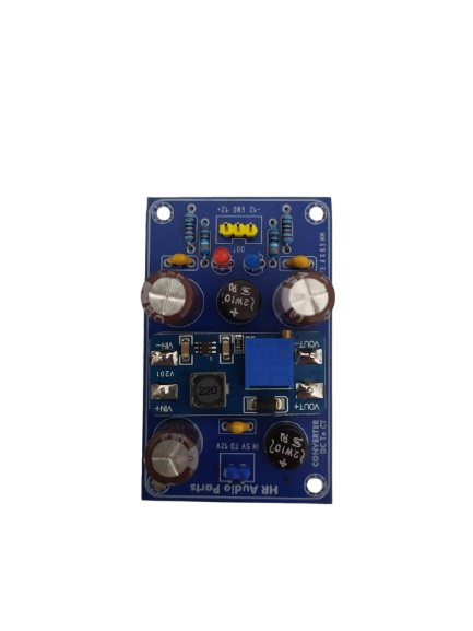
Pin Configuration and Descriptions
Below is a typical pinout for a DC-DC buck konverter module:
| Pin Name | Description |
|---|---|
| VIN | Input voltage pin. Connect the power source here (e.g., battery or adapter). |
| GND | Ground pin. Connect to the ground of the circuit. |
| VOUT | Output voltage pin. Provides the regulated output voltage. |
| EN (Enable) | Enable pin. Used to turn the converter on or off (optional, depending on model). |
Usage Instructions
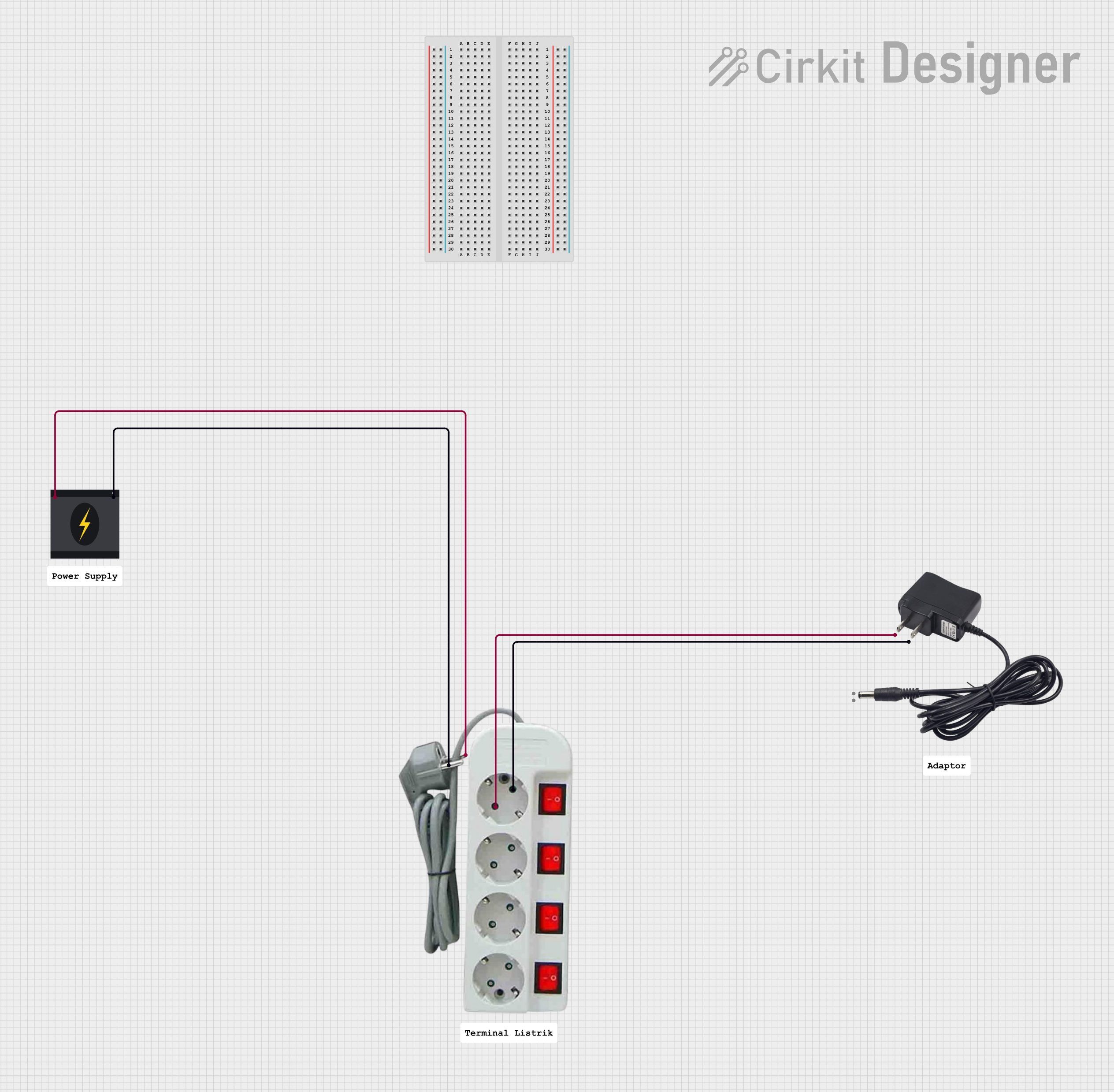
How to Use the Konverter in a Circuit
- Connect the Input Voltage: Attach the power source to the
VINandGNDpins. Ensure the input voltage is within the specified range. - Set the Output Voltage: If the konverter has an adjustable output, use the onboard potentiometer to set the desired output voltage. Use a multimeter to measure the output voltage for accuracy.
- Connect the Load: Attach the device or circuit to the
VOUTandGNDpins. Ensure the load does not exceed the maximum current rating of the konverter. - Enable the Konverter: If the module has an
ENpin, connect it to a high logic level (e.g., 5V) to enable the output. Leave it unconnected or connect it to ground to disable the module.
Important Considerations and Best Practices
- Heat Dissipation: For high-current applications, ensure proper heat dissipation using heatsinks or active cooling.
- Input Voltage: Always verify that the input voltage is within the specified range to avoid damage.
- Output Filtering: Add capacitors at the output to reduce noise and improve stability.
- Polarity: Double-check the polarity of connections to avoid damaging the module.
Example: Using a Konverter with an Arduino UNO
Below is an example of using a DC-DC konverter to power an Arduino UNO from a 12V battery:
- Connect the 12V battery to the
VINandGNDpins of the konverter. - Adjust the output voltage to 5V using the potentiometer.
- Connect the
VOUTpin of the konverter to the5Vpin of the Arduino UNO. - Connect the
GNDpin of the konverter to theGNDpin of the Arduino UNO.
Here is a simple Arduino code to blink an LED, powered by the konverter:
// Simple LED Blink Example
// This code assumes the Arduino UNO is powered by a konverter set to 5V.

const int ledPin = 13; // Built-in LED pin on Arduino UNO

void setup() {
  pinMode(ledPin, OUTPUT); // Set the LED pin as an output
}

void loop() {
  digitalWrite(ledPin, HIGH); // Turn the LED on
  delay(1000);               // Wait for 1 second
  digitalWrite(ledPin, LOW);  // Turn the LED off
  delay(1000);               // Wait for 1 second
}
Troubleshooting and FAQs
Common Issues and Solutions
No Output Voltage:
- Cause: Input voltage is not connected or is out of range.
- Solution: Verify the input voltage and connections.
Overheating:
- Cause: Excessive current draw or insufficient cooling.
- Solution: Reduce the load or add a heatsink to the konverter.
Unstable Output Voltage:
- Cause: Insufficient input or output filtering.
- Solution: Add capacitors (e.g., 100µF electrolytic and 0.1µF ceramic) to the input and output.
Device Not Powering On:
- Cause: Incorrect polarity or loose connections.
- Solution: Double-check all connections and ensure correct polarity.
FAQs
Q: Can I use a konverter to power sensitive electronics?
A: Yes, but ensure the output voltage is stable and within the device's tolerance. Adding filtering capacitors can help.Q: What happens if I exceed the maximum current rating?
A: The konverter may overheat, shut down, or become permanently damaged. Always stay within the specified limits.Q: Can I use a konverter to step up voltage?
A: No, a buck konverter is designed to step down voltage. Use a boost konverter for stepping up voltage.Q: How do I know if my konverter is working correctly?
A: Measure the output voltage with a multimeter and ensure it matches the desired value.
This documentation provides a comprehensive guide to understanding and using a konverter effectively. Always refer to the specific datasheet of your konverter model for precise details.