How to Use Prototype PCB Solderable Breadboard: Examples, Pinouts, and Specs
Introduction
The Prototype PCB Solderable Breadboard (Manufacturer Part ID: ECPB_H_BK'_5P) by ElectroCookie is a versatile prototyping tool designed for building and testing electronic circuits. It combines the convenience of a traditional breadboard layout with the durability of a solderable PCB, allowing users to transition from temporary setups to permanent solutions seamlessly. This component is ideal for hobbyists, students, and professionals working on electronic projects.
Explore Projects Built with Prototype PCB Solderable Breadboard
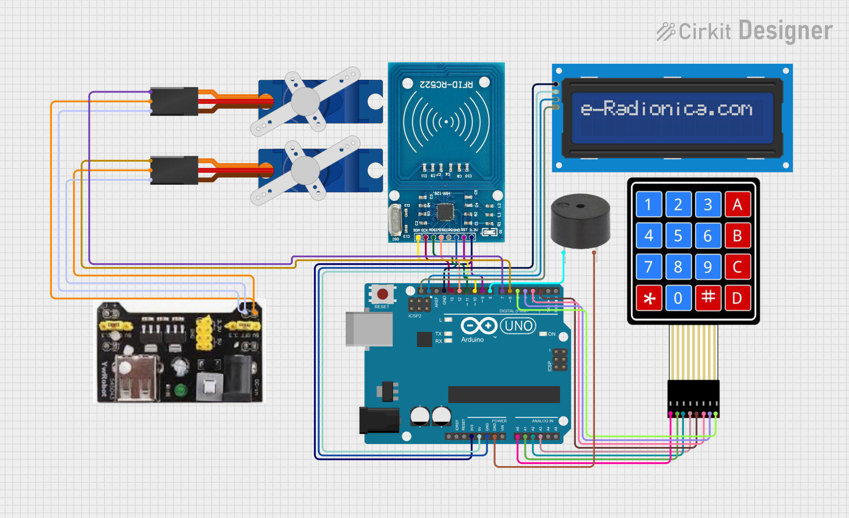
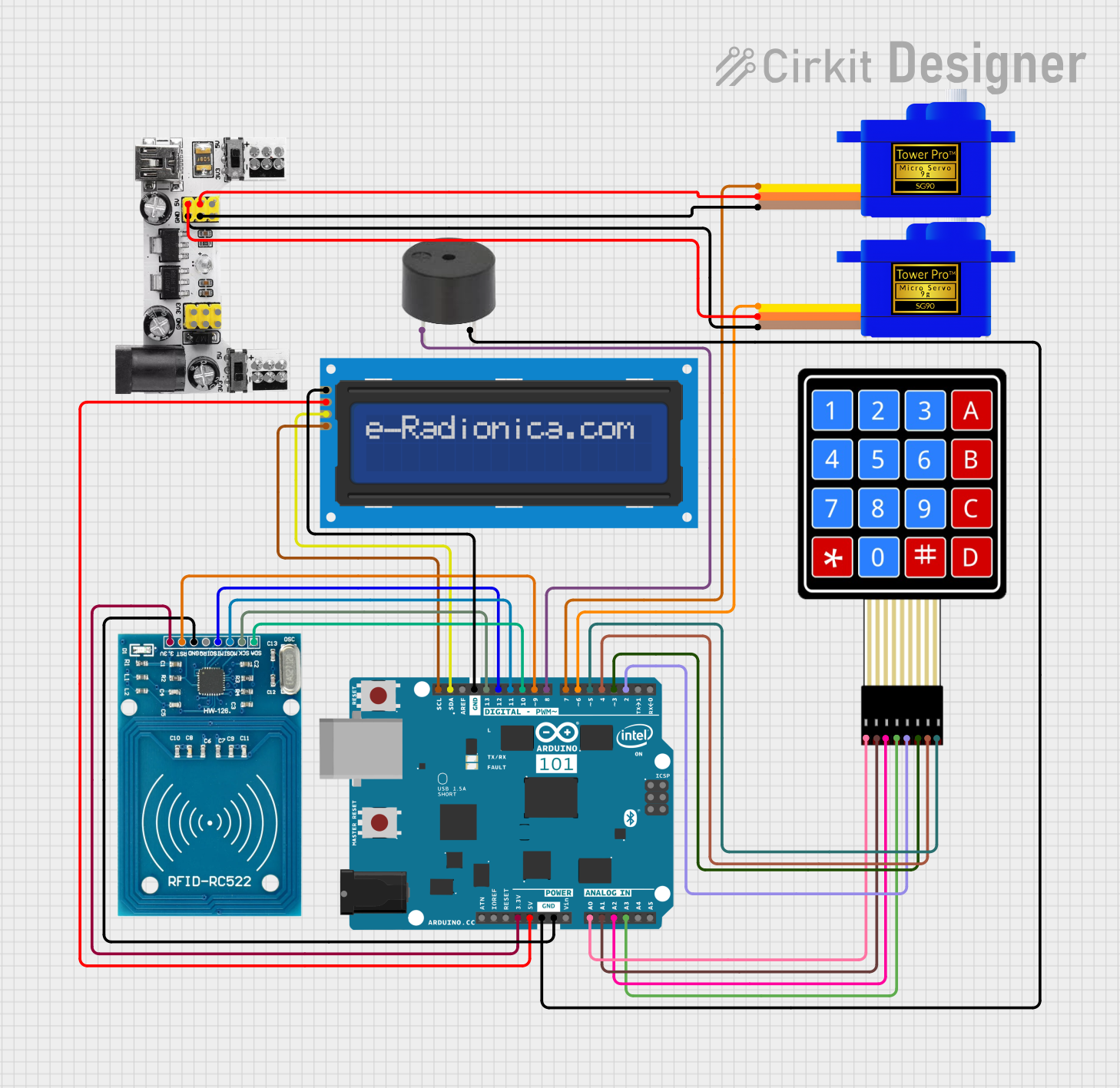

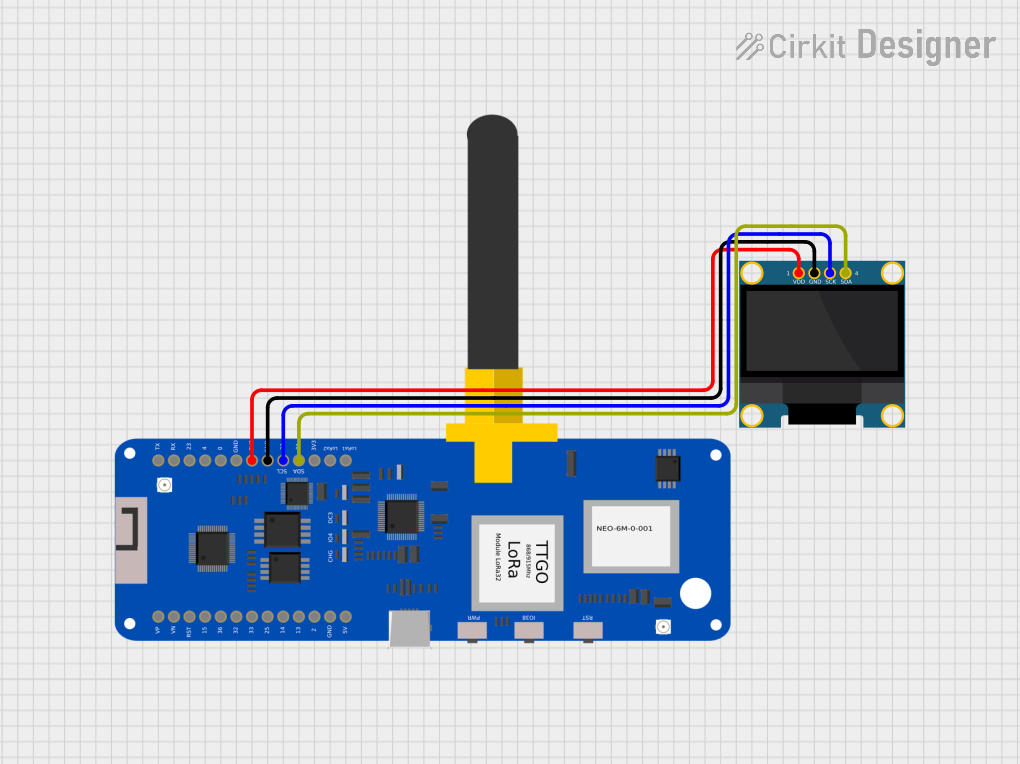
Explore Projects Built with Prototype PCB Solderable Breadboard
Common Applications and Use Cases
- Prototyping and testing electronic circuits.
- Transitioning from breadboard designs to permanent soldered circuits.
- Educational projects for learning circuit design and soldering techniques.
- Compact and durable circuit assembly for DIY electronics.
Technical Specifications
The Prototype PCB Solderable Breadboard is designed to mimic the layout of a standard breadboard while providing solderable pads for permanent connections. Below are the key technical details:
General Specifications
| Parameter | Value |
|---|---|
| Manufacturer | ElectroCookie |
| Part ID | ECPB_H_BK'_5P |
| Material | FR4 (Fiberglass PCB) |
| Dimensions | 3.2 in x 2.1 in (82 mm x 53 mm) |
| Thickness | 1.6 mm |
| Pad Plating | Lead-free HASL (Solderable) |
| Hole Diameter | 1.0 mm |
| Grid Spacing | 2.54 mm (0.1 in) |
| Number of Holes | 400+ |
| Operating Temperature | -40°C to 85°C |
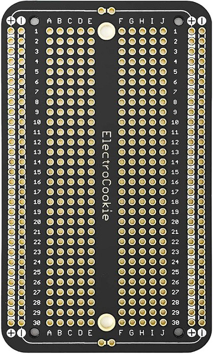
Layout and Pin Configuration
The board layout is designed to replicate a standard breadboard, with power rails and terminal strips. Below is a description of the sections:
| Section | Description |
|---|---|
| Power Rails | Two rows on each side for power and ground connections. |
| Terminal Strips | Central area with a grid of solderable pads for component connections. |
| Mounting Holes | Four corner holes for securing the board to enclosures or workbenches. |
Usage Instructions
How to Use the Component in a Circuit
- Plan Your Circuit: Sketch your circuit design on paper or using software. Ensure the layout fits within the available grid.
- Place Components: Insert components into the holes, ensuring proper alignment with the grid.
- Solder Connections:
- Heat the soldering iron to the appropriate temperature (typically 350°C for lead-free solder).
- Apply solder to the component leads and pads to create secure connections.
- Connect Power Rails: Use jumper wires to connect the power and ground rails to your power source.
- Test the Circuit: Verify the functionality of your circuit before finalizing the design.
Important Considerations and Best Practices
- Avoid Overheating: Excessive heat can damage the PCB or components. Use a temperature-controlled soldering iron.
- Use Flux: Apply flux to improve solder flow and ensure clean connections.
- Check Connections: Inspect solder joints for cold soldering or shorts.
- Label Connections: Use markers or labels to identify power, ground, and signal lines for easier debugging.
- Arduino Compatibility: The board is compatible with Arduino projects. Use male headers to connect the board to an Arduino UNO.
Example: Connecting an LED Circuit to Arduino UNO
Below is an example of how to use the solderable breadboard to connect an LED to an Arduino UNO:
// Arduino LED Blink Example
// This code blinks an LED connected to pin 13 of the Arduino UNO.
// Ensure the LED's longer leg (anode) is connected to pin 13 and the shorter
// leg (cathode) is connected to ground via a 220-ohm resistor.

void setup() {
  pinMode(13, OUTPUT); // Set pin 13 as an output pin
}

void loop() {
  digitalWrite(13, HIGH); // Turn the LED on
  delay(1000);            // Wait for 1 second
  digitalWrite(13, LOW);  // Turn the LED off
  delay(1000);            // Wait for 1 second
}
Tips for Arduino Projects
- Use male headers to connect the breadboard to the Arduino for easy prototyping.
- Ensure proper grounding between the Arduino and the breadboard.
Troubleshooting and FAQs
Common Issues and Solutions
| Issue | Possible Cause | Solution |
|---|---|---|
| Solder not sticking to pads | Dirty or oxidized pads | Clean pads with isopropyl alcohol or flux. |
| Components not functioning | Incorrect connections or solder bridges | Verify connections and inspect for shorts. |
| Overheating components | Excessive soldering time or wrong polarity | Check soldering technique and polarity. |
| Power rails not working | Missing or loose jumper wires | Ensure proper connections to power source. |
FAQs
Q: Can I reuse the board after soldering?
A: While the board is designed for permanent connections, you can desolder components and reuse the board if needed. However, repeated desoldering may degrade the pads.
Q: Is the board compatible with surface-mount components?
A: The board is primarily designed for through-hole components. However, with careful soldering, small SMD components can be used.
Q: How do I secure the board to a project enclosure?
A: Use the mounting holes in the corners to attach the board to an enclosure with screws or standoffs.
Q: Can I cut the board to a smaller size?
A: Yes, the board can be cut using a hacksaw or rotary tool. Ensure to smooth the edges after cutting.
By following this documentation, you can effectively use the Prototype PCB Solderable Breadboard for your electronic projects, ensuring reliable and durable circuit designs.