How to Use Régulateur de tension: Examples, Pinouts, and Specs
Introduction
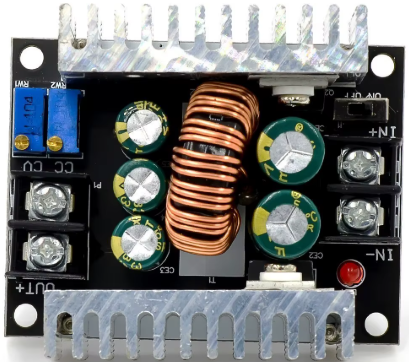
A voltage regulator is a device used to maintain a constant voltage level in an electrical circuit, despite variations in load or input voltage. Voltage regulators are essential in ensuring the stable operation of electronic devices by providing a consistent voltage supply. They are commonly used in power supplies, battery chargers, and various electronic circuits to protect sensitive components from voltage fluctuations.
Explore Projects Built with Régulateur de tension


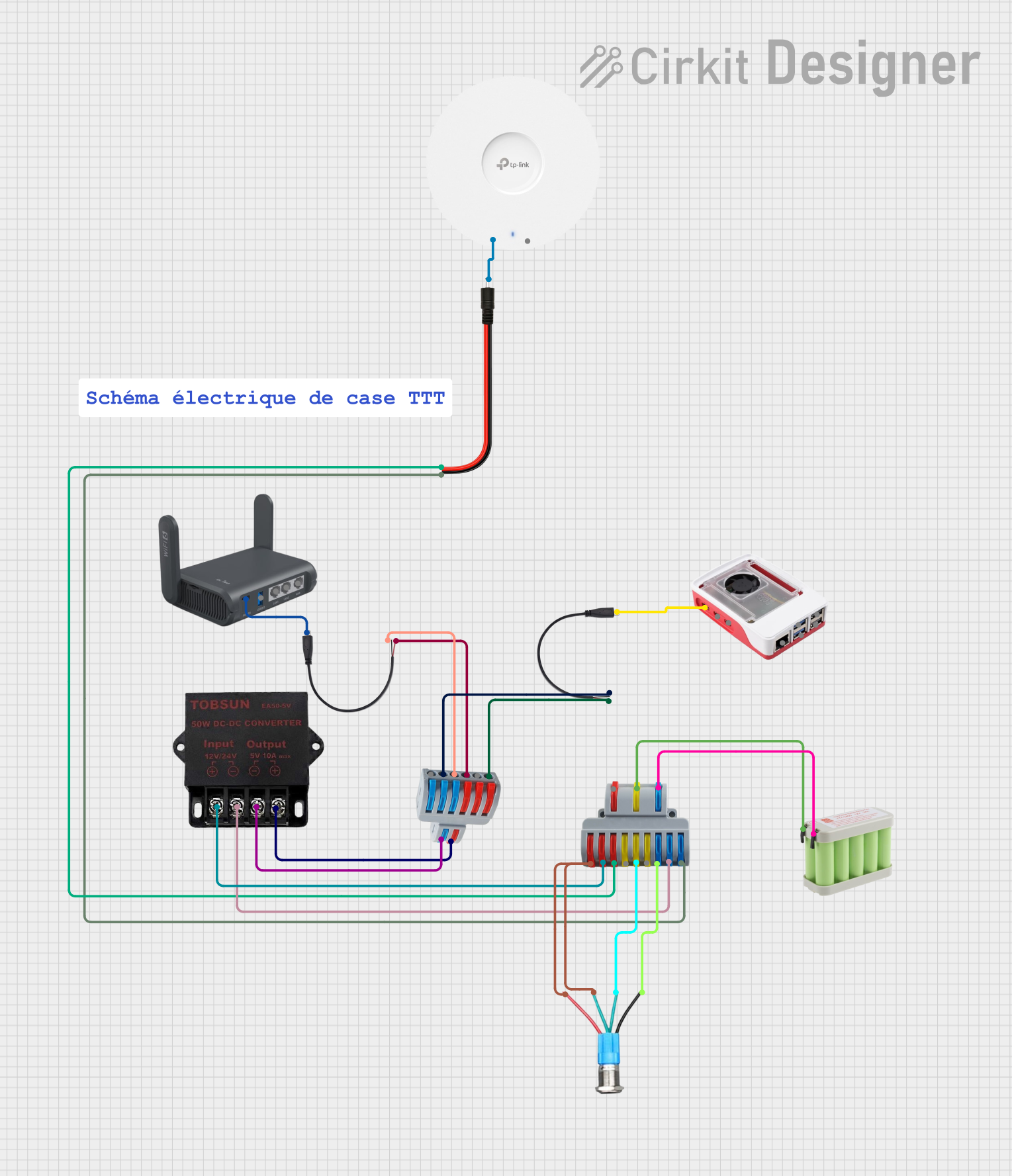
Explore Projects Built with Régulateur de tension
Technical Specifications
Key Technical Details
| Parameter | Value |
|---|---|
| Input Voltage Range | 7V to 35V |
| Output Voltage | 5V (fixed) |
| Output Current | 1.5A (maximum) |
| Power Dissipation | 15W |
| Dropout Voltage | 2V |
| Operating Temperature Range | -40°C to 125°C |
Pin Configuration and Descriptions
| Pin Number | Pin Name | Description |
|---|---|---|
| 1 | Input | Input voltage (7V to 35V) |
| 2 | Ground | Ground (0V) |
| 3 | Output | Regulated output voltage (5V) |
Usage Instructions
How to Use the Component in a Circuit
Connect the Input Voltage:
- Connect the input voltage (ranging from 7V to 35V) to the Input pin of the voltage regulator.
Connect the Ground:
- Connect the Ground pin of the voltage regulator to the ground of the circuit.
Connect the Output Voltage:
- Connect the Output pin of the voltage regulator to the load or the circuit that requires a regulated 5V supply.
Important Considerations and Best Practices
Heat Dissipation:
- Ensure proper heat dissipation by using a heatsink if the regulator is expected to dissipate significant power.
Capacitors:
- Use input and output capacitors (typically 0.33µF and 0.1µF respectively) to improve stability and transient response.
Load Current:
- Ensure that the load current does not exceed the maximum output current rating of 1.5A.
Dropout Voltage:
- Ensure that the input voltage is at least 2V higher than the desired output voltage to maintain proper regulation.
Example Circuit with Arduino UNO
Here is an example of how to use a voltage regulator to power an Arduino UNO:
Circuit Diagram
+12V ----->| Input (Pin 1)
           |
           |----->| Output (Pin 3) ----->| 5V Pin on Arduino UNO
           |
          GND (Pin 2) ----->| GND on Arduino UNO
Arduino Code Example
// Simple Arduino code to blink an LED connected to pin 13

void setup() {
  pinMode(13, OUTPUT); // Set pin 13 as an output
}

void loop() {
  digitalWrite(13, HIGH); // Turn the LED on
  delay(1000);            // Wait for 1 second
  digitalWrite(13, LOW);  // Turn the LED off
  delay(1000);            // Wait for 1 second
}
Troubleshooting and FAQs
Common Issues Users Might Face
Overheating:
- If the voltage regulator becomes too hot, it may shut down to protect itself. Ensure proper heat dissipation using a heatsink.
Output Voltage Not Stable:
- Check the input voltage to ensure it is within the specified range.
- Verify that the input and output capacitors are correctly placed and have the correct values.
No Output Voltage:
- Ensure that the input voltage is connected and within the specified range.
- Check for proper connections and ensure that the ground is correctly connected.
Solutions and Tips for Troubleshooting
Check Connections:
- Verify all connections to ensure they are secure and correctly placed.
Measure Voltages:
- Use a multimeter to measure the input and output voltages to ensure they are within the expected ranges.
Use Proper Components:
- Ensure that the capacitors used are of the correct type and value as recommended in the datasheet.
By following these guidelines and best practices, you can effectively use a voltage regulator to maintain a stable voltage supply in your electronic circuits.