How to Use MAX78000: Examples, Pinouts, and Specs
Introduction
The MAX78000 is a low-power, high-performance microcontroller specifically designed for machine learning (ML) applications. It features an integrated neural network accelerator, which allows for efficient execution of AI algorithms directly on edge devices. This capability makes the MAX78000 ideal for applications requiring real-time decision-making, such as image recognition, voice processing, and anomaly detection, without relying on cloud-based processing.
Explore Projects Built with MAX78000


Explore Projects Built with MAX78000
Common Applications and Use Cases
- Image and Object Recognition: Real-time image classification and object detection.
- Voice and Audio Processing: Wake-word detection, speech recognition, and audio classification.
- IoT Devices: Smart home devices, industrial monitoring, and predictive maintenance.
- Wearable Technology: Health monitoring and fitness tracking with AI-based insights.
- Edge AI Systems: Applications requiring low-latency AI processing with minimal power consumption.
Technical Specifications
Key Technical Details
| Parameter | Value |
|---|---|
| Core Architecture | Arm Cortex-M4 with FPU (floating-point unit) |
| Neural Network Accelerator | 64x64 MAC (Multiply-Accumulate) array for AI inference |
| Flash Memory | 512 KB |
| SRAM | 128 KB |
| Neural Network Memory | 442 KB |
| Operating Voltage | 1.8V to 3.3V |
| Power Consumption | 1 mW (typical for AI inference tasks) |
| GPIO Pins | 32 |
| Communication Interfaces | I2C, SPI, UART, I2S, and USB |
| Clock Speed | 100 MHz (Cortex-M4 core) |
| Package | 81-pin WLP (Wafer-Level Package) |
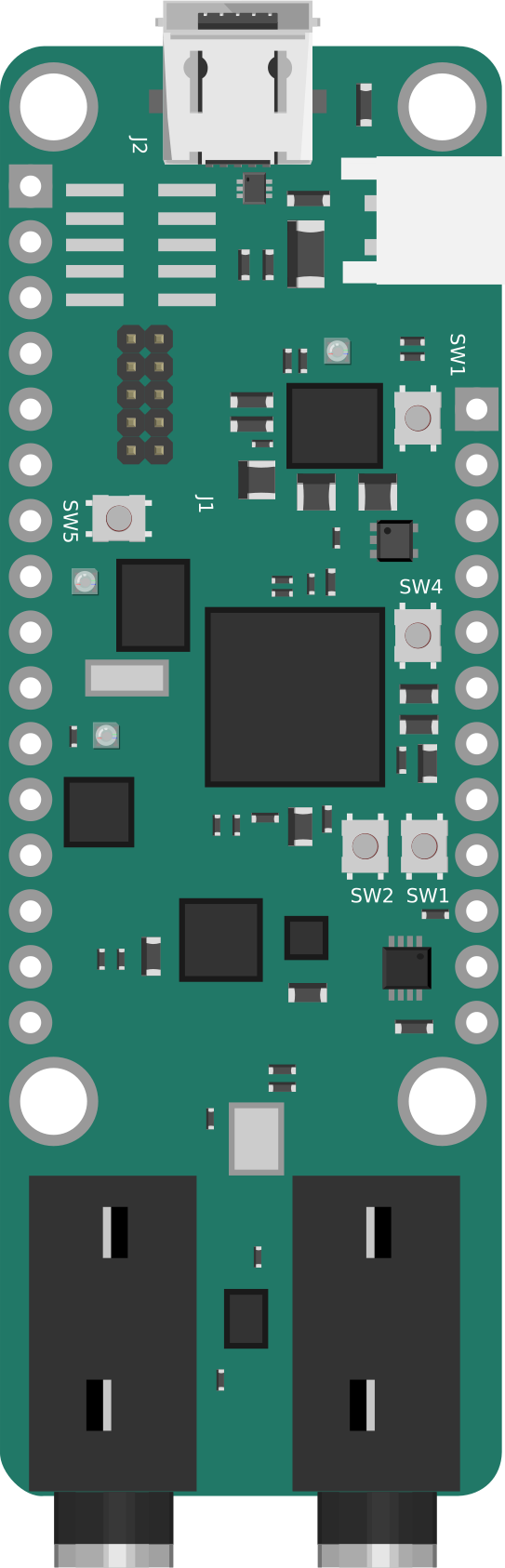
Pin Configuration and Descriptions
| Pin Name | Type | Description |
|---|---|---|
| VDD | Power | Main power supply (1.8V to 3.3V). |
| GND | Ground | Ground connection. |
| GPIO[0-31] | Digital I/O | General-purpose input/output pins. Configurable for various functions. |
| UART_TX | Digital Output | UART transmit pin for serial communication. |
| UART_RX | Digital Input | UART receive pin for serial communication. |
| I2C_SCL | Digital I/O | I2C clock line. |
| I2C_SDA | Digital I/O | I2C data line. |
| SPI_MOSI | Digital Output | SPI Master Out Slave In. |
| SPI_MISO | Digital Input | SPI Master In Slave Out. |
| SPI_SCK | Digital Output | SPI clock line. |
| USB_DP | Analog I/O | USB data positive. |
| USB_DM | Analog I/O | USB data negative. |
| RESET | Digital Input | Active-low reset pin. |
Usage Instructions
How to Use the MAX78000 in a Circuit
- Power Supply: Connect the VDD pin to a stable power source (1.8V to 3.3V) and GND to ground.
- Peripheral Connections: Use the GPIO pins for interfacing with external devices such as sensors, actuators, or displays. Configure the pins as needed (input, output, or alternate functions).
- Neural Network Deployment:
- Train your neural network model using a supported framework (e.g., TensorFlow Lite).
- Convert the model to a format compatible with the MAX78000 using the Maxim Integrated tools.
- Load the model onto the MAX78000 using the provided SDK and development tools.
- Communication Interfaces: Use I2C, SPI, UART, or USB for communication with other devices or microcontrollers.
- Programming: Write and upload firmware using the Maxim Integrated IDE or other supported development environments.
Important Considerations and Best Practices
- Power Management: Leverage the MAX78000's low-power modes to optimize energy consumption in battery-powered applications.
- Thermal Management: Ensure proper heat dissipation if the device is used in high-performance or continuous operation scenarios.
- Model Optimization: Use quantization and pruning techniques to reduce the size and complexity of neural network models for efficient execution.
- Debugging: Use the integrated JTAG interface for debugging and troubleshooting during development.
Example: Using MAX78000 with Arduino UNO
While the MAX78000 is not directly compatible with Arduino IDE, it can communicate with an Arduino UNO via UART. Below is an example of Arduino code to send data to the MAX78000:
// Example: Sending data from Arduino UNO to MAX78000 via UART

void setup() {
  Serial.begin(115200); // Initialize UART communication at 115200 baud rate
}

void loop() {
  // Send a test message to the MAX78000
  Serial.println("Hello, MAX78000!");

  // Wait for 1 second before sending the next message
  delay(1000);
}
On the MAX78000 side, you can use its UART interface to receive and process the data.
Troubleshooting and FAQs
Common Issues and Solutions
Issue: The MAX78000 does not power on.
- Solution: Verify that the VDD pin is connected to a stable power source within the specified voltage range (1.8V to 3.3V). Check all ground connections.
Issue: Neural network inference is slow or fails.
- Solution: Ensure the model is optimized for the MAX78000's neural network accelerator. Use the Maxim Integrated tools to convert and optimize the model.
Issue: Communication with external devices fails.
- Solution: Double-check the pin configurations and ensure the correct communication protocol (I2C, SPI, UART) is being used. Verify pull-up resistors for I2C lines if needed.
Issue: Overheating during operation.
- Solution: Check for proper ventilation and ensure the device is not operating beyond its power and performance limits.
FAQs
Q: Can the MAX78000 run any neural network model?
- A: The MAX78000 supports models that are optimized and converted using Maxim Integrated's tools. Ensure the model fits within the available memory and is compatible with the neural network accelerator.
Q: What development tools are available for the MAX78000?
- A: Maxim Integrated provides an SDK, IDE, and model conversion tools for developing and deploying applications on the MAX78000.
Q: Can the MAX78000 interface with other microcontrollers?
- A: Yes, the MAX78000 can communicate with other microcontrollers via UART, I2C, SPI, or USB interfaces.
Q: Is the MAX78000 suitable for battery-powered devices?
- A: Yes, the MAX78000 is designed for low-power operation, making it ideal for battery-powered and portable applications.