Cirkit Designer
Your all-in-one circuit design IDE
Home /
Component Documentation
How to Use Contactor Symbol: Examples, Pinouts, and Specs

Introduction
A contactor symbol represents an electrically-controlled switch used for switching an electrical power circuit. It is similar to a relay but is designed to handle higher current ratings. Contactors are widely used in industrial applications for controlling electric motors, lighting, heating, capacitor banks, and other electrical loads.
Explore Projects Built with Contactor Symbol
Electromechanical Pump Control Circuit with Emergency Stop

This circuit is designed to control a pump using a contactor that is manually operated by a switch and can be overridden by an emergency stop. The contactor enables power from an AC power outlet to the pump, and the emergency stop can interrupt the power circuit for safety purposes.
Industrial Power Distribution and Safety Control System

This circuit is designed for power distribution and safety control in an industrial setting. It features a main isolator and circuit breaker for power management, multiple PSUs for 5V, 12V, and 24V outputs, and a safety relay system that interfaces with E-stop buttons and a start switch to control a main contactor, ensuring safe operation and emergency power cut-off capabilities.
ESP32-Controlled Smart Relay with Touch Activation and OLED Feedback
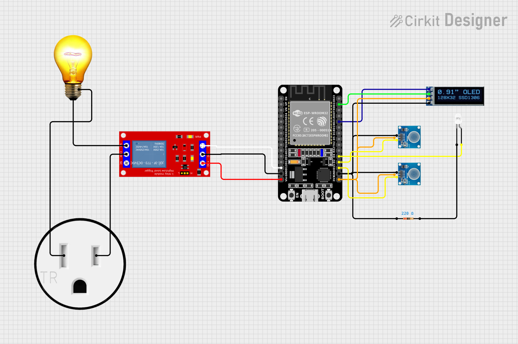
This circuit features an ESP32 microcontroller connected to a relay module, an OLED display, two touch sensors, an LED with a current-limiting resistor, and an AC bulb connected to a 120V outlet. The ESP32 likely controls the relay to switch the AC bulb on and off, receives touch inputs, drives the OLED display for user interface, and controls the LED as an indicator. The absence of code suggests that the specific logic for interaction between these components is not yet implemented.
Pushbutton-Controlled Interface with 40-Pin Connector and UBS Power Supply

This circuit consists of a 40-pin connector interfacing with four pushbuttons and a UBS power supply. The pushbuttons are used as inputs to the connector, which then relays the signals to other components or systems. The UBS power supply provides the necessary 24V power to the pushbuttons and the common ground for the circuit.
Explore Projects Built with Contactor Symbol
Electromechanical Pump Control Circuit with Emergency Stop
This circuit is designed to control a pump using a contactor that is manually operated by a switch and can be overridden by an emergency stop. The contactor enables power from an AC power outlet to the pump, and the emergency stop can interrupt the power circuit for safety purposes.
Industrial Power Distribution and Safety Control System
This circuit is designed for power distribution and safety control in an industrial setting. It features a main isolator and circuit breaker for power management, multiple PSUs for 5V, 12V, and 24V outputs, and a safety relay system that interfaces with E-stop buttons and a start switch to control a main contactor, ensuring safe operation and emergency power cut-off capabilities.
ESP32-Controlled Smart Relay with Touch Activation and OLED Feedback
This circuit features an ESP32 microcontroller connected to a relay module, an OLED display, two touch sensors, an LED with a current-limiting resistor, and an AC bulb connected to a 120V outlet. The ESP32 likely controls the relay to switch the AC bulb on and off, receives touch inputs, drives the OLED display for user interface, and controls the LED as an indicator. The absence of code suggests that the specific logic for interaction between these components is not yet implemented.
Pushbutton-Controlled Interface with 40-Pin Connector and UBS Power Supply
This circuit consists of a 40-pin connector interfacing with four pushbuttons and a UBS power supply. The pushbuttons are used as inputs to the connector, which then relays the signals to other components or systems. The UBS power supply provides the necessary 24V power to the pushbuttons and the common ground for the circuit.
Technical Specifications
Key Technical Details
| Parameter | Value |
|---|---|
| Voltage Rating | 24V, 48V, 110V, 220V, 380V |
| Current Rating | 9A, 12A, 18A, 25A, 32A, 40A |
| Power Rating | Up to 75 kW |
| Coil Voltage | 24V DC, 48V DC, 110V AC, 220V AC |
| Contact Configuration | 3P, 4P, 2NO+2NC, 3NO+1NC |
| Mechanical Life | 10 million operations |
| Electrical Life | 1 million operations |
Pin Configuration and Descriptions
| Pin Number | Pin Name | Description |
|---|---|---|
| 1 | A1 | Coil Terminal 1 |
| 2 | A2 | Coil Terminal 2 |
| 3 | NO1 | Normally Open Contact 1 |
| 4 | NO2 | Normally Open Contact 2 |
| 5 | NO3 | Normally Open Contact 3 |
| 6 | NC1 | Normally Closed Contact 1 |
| 7 | NC2 | Normally Closed Contact 2 |
| 8 | NC3 | Normally Closed Contact 3 |
| 9 | COM1 | Common Terminal 1 |
| 10 | COM2 | Common Terminal 2 |
| 11 | COM3 | Common Terminal 3 |
Usage Instructions
How to Use the Contactor in a Circuit
Power Supply Connection:
- Connect the coil terminals (A1 and A2) to the appropriate control voltage (e.g., 24V DC or 220V AC).
- Ensure the power supply matches the coil voltage rating of the contactor.
Load Connection:
- Connect the load to the normally open (NO) or normally closed (NC) contacts based on the desired operation.
- For example, connect the load to NO1 and COM1 for a normally open configuration.
Control Signal:
- Use a control signal (e.g., from a microcontroller or switch) to energize the coil and activate the contactor.
- When the coil is energized, the NO contacts will close, and the NC contacts will open.
Important Considerations and Best Practices
- Voltage and Current Ratings: Ensure the contactor's voltage and current ratings match the requirements of your application.
- Heat Dissipation: Provide adequate ventilation and cooling to prevent overheating.
- Wiring: Use appropriate wire gauges and secure connections to avoid loose contacts.
- Safety: Always follow safety guidelines and disconnect power before making any connections.
Example: Connecting a Contactor to an Arduino UNO
To control a contactor using an Arduino UNO, you can use a transistor to drive the contactor coil. Below is an example circuit and code:
Circuit Diagram
- Connect the Arduino digital pin (e.g., D7) to the base of an NPN transistor through a 1kΩ resistor.
- Connect the emitter of the transistor to ground.
- Connect the collector of the transistor to one terminal of the contactor coil (A1).
- Connect the other terminal of the contactor coil (A2) to the positive power supply (e.g., 24V DC).
- Connect the ground of the power supply to the Arduino ground.
Arduino Code
// Define the pin connected to the transistor base
const int contactorPin = 7;

void setup() {
  // Set the contactor pin as an output
  pinMode(contactorPin, OUTPUT);
}

void loop() {
  // Energize the contactor coil
  digitalWrite(contactorPin, HIGH);
  delay(1000); // Keep the contactor energized for 1 second

  // De-energize the contactor coil
  digitalWrite(contactorPin, LOW);
  delay(1000); // Keep the contactor de-energized for 1 second
}
Troubleshooting and FAQs
Common Issues Users Might Face
Contactor Not Energizing:
- Check the control voltage and ensure it matches the coil voltage rating.
- Verify the connections and ensure the control signal is reaching the coil.
Overheating:
- Ensure proper ventilation and cooling.
- Check for overcurrent conditions and use appropriate wire gauges.
Noise and Chattering:
- Ensure a stable control voltage.
- Check for loose connections and secure them properly.
Solutions and Tips for Troubleshooting
- Check Power Supply: Ensure the power supply voltage is stable and within the specified range.
- Inspect Connections: Verify all connections are secure and free from corrosion.
- Use Proper Components: Ensure the contactor and associated components are rated for the application.
- Consult Datasheets: Refer to the manufacturer's datasheet for detailed specifications and guidelines.
By following this documentation, users can effectively utilize contactors in their electrical circuits, ensuring reliable and safe operation.