Cirkit Designer Logo
Cirkit Designer
Your all-in-one circuit design IDE
Home / 
Component Documentation

How to Use ZMCT103C CURRENT SENSOR: Examples, Pinouts, and Specs

Image of ZMCT103C CURRENT SENSOR
Cirkit Designer LogoDesign with ZMCT103C CURRENT SENSOR in Cirkit Designer

Introduction

The ZMCT103C current sensor is a compact, high-precision device designed for measuring AC current up to a specified range. This sensor is widely used in power monitoring systems, energy management applications, and for current monitoring in various electronic projects. Its small form factor and ease of use make it a popular choice for hobbyists and professionals alike.

Explore Projects Built with ZMCT103C CURRENT SENSOR

Use Cirkit Designer to design, explore, and prototype these projects online. Some projects support real-time simulation. Click "Open Project" to start designing instantly!
ESP32-Based Smart Energy Monitoring and Control System
Image of SMART SOCKET: A project utilizing ZMCT103C CURRENT SENSOR in a practical application
This circuit is designed to monitor AC voltage and current using ZMPT101B and ZMCT103C sensors, respectively, with an ESP32 microcontroller processing the sensor outputs. The XL4015 step-down module regulates the power supply to provide a stable voltage to the sensors, the ESP32, and an LCD I2C display. The ESP32 controls a 4-channel relay module for switching AC loads, and the system's operation can be interacted with via the LCD display and a push switch.
Cirkit Designer LogoOpen Project in Cirkit Designer
Wi-Fi Controlled Power Monitoring and Relay System using ESP8266, ACS712, and ZMPT101B
Image of LOAD MONITORING: A project utilizing ZMCT103C CURRENT SENSOR in a practical application
This circuit is designed for monitoring electrical parameters using an ESP8266 microcontroller. It includes an ACS712 current sensor and a ZMPT101B voltage sensor to measure current and voltage, respectively, with the data being multiplexed through a CD4051 multiplexer and controlled by the ESP8266. Additionally, a 5V relay is included for switching purposes, controlled by the ESP8266.
Cirkit Designer LogoOpen Project in Cirkit Designer
Wemos S2 Mini Controlled Smart Device with OLED Display, Thermal Printing, and RGB LED Strip
Image of DT NEA - Noah Patel: A project utilizing ZMCT103C CURRENT SENSOR in a practical application
This circuit features a Wemos S2 Mini microcontroller that controls a WS2812 RGB LED strip and communicates with a 0.96" OLED display and a 58mm mini thermal printer. The ACS712 Current Sensor is interfaced with the microcontroller to monitor current, and power is managed by a CD42 BMS connected to two 18650 Li-ion batteries, with a USB-C PD Trigger Board for power delivery. The circuit is designed for visual output (LED strip, OLED display), printing capabilities, and current sensing, likely for a portable, battery-powered monitoring and display device.
Cirkit Designer LogoOpen Project in Cirkit Designer
ESP32-Based Smart Power Monitoring System with Wi-Fi Connectivity
Image of Alaa : A project utilizing ZMCT103C CURRENT SENSOR in a practical application
This circuit is designed to monitor and measure electrical parameters using an ESP32 microcontroller, a ZMPT101B voltage sensor, and a 5A current sensor. It includes visual indicators with red and green LEDs and an audible alert via a piezo buzzer, all controlled by the ESP32.
Cirkit Designer LogoOpen Project in Cirkit Designer

Explore Projects Built with ZMCT103C CURRENT SENSOR

Use Cirkit Designer to design, explore, and prototype these projects online. Some projects support real-time simulation. Click "Open Project" to start designing instantly!
Image of SMART SOCKET: A project utilizing ZMCT103C CURRENT SENSOR in a practical application
ESP32-Based Smart Energy Monitoring and Control System
This circuit is designed to monitor AC voltage and current using ZMPT101B and ZMCT103C sensors, respectively, with an ESP32 microcontroller processing the sensor outputs. The XL4015 step-down module regulates the power supply to provide a stable voltage to the sensors, the ESP32, and an LCD I2C display. The ESP32 controls a 4-channel relay module for switching AC loads, and the system's operation can be interacted with via the LCD display and a push switch.
Cirkit Designer LogoOpen Project in Cirkit Designer
Image of LOAD MONITORING: A project utilizing ZMCT103C CURRENT SENSOR in a practical application
Wi-Fi Controlled Power Monitoring and Relay System using ESP8266, ACS712, and ZMPT101B
This circuit is designed for monitoring electrical parameters using an ESP8266 microcontroller. It includes an ACS712 current sensor and a ZMPT101B voltage sensor to measure current and voltage, respectively, with the data being multiplexed through a CD4051 multiplexer and controlled by the ESP8266. Additionally, a 5V relay is included for switching purposes, controlled by the ESP8266.
Cirkit Designer LogoOpen Project in Cirkit Designer
Image of DT NEA - Noah Patel: A project utilizing ZMCT103C CURRENT SENSOR in a practical application
Wemos S2 Mini Controlled Smart Device with OLED Display, Thermal Printing, and RGB LED Strip
This circuit features a Wemos S2 Mini microcontroller that controls a WS2812 RGB LED strip and communicates with a 0.96" OLED display and a 58mm mini thermal printer. The ACS712 Current Sensor is interfaced with the microcontroller to monitor current, and power is managed by a CD42 BMS connected to two 18650 Li-ion batteries, with a USB-C PD Trigger Board for power delivery. The circuit is designed for visual output (LED strip, OLED display), printing capabilities, and current sensing, likely for a portable, battery-powered monitoring and display device.
Cirkit Designer LogoOpen Project in Cirkit Designer
Image of Alaa : A project utilizing ZMCT103C CURRENT SENSOR in a practical application
ESP32-Based Smart Power Monitoring System with Wi-Fi Connectivity
This circuit is designed to monitor and measure electrical parameters using an ESP32 microcontroller, a ZMPT101B voltage sensor, and a 5A current sensor. It includes visual indicators with red and green LEDs and an audible alert via a piezo buzzer, all controlled by the ESP32.
Cirkit Designer LogoOpen Project in Cirkit Designer

Common Applications and Use Cases

  • Home energy monitoring systems
  • Industrial automation
  • Overcurrent protection circuits
  • Smart power management in IoT devices
  • Electrical load monitoring

Technical Specifications

Key Technical Details

  • Input Current Range: 0 to 5A AC
  • Output Voltage: 0 to 1V (linearly proportional to AC current)
  • Supply Voltage: 5V to 30V DC
  • Accuracy: ±1%
  • Operating Temperature: -40°C to +85°C

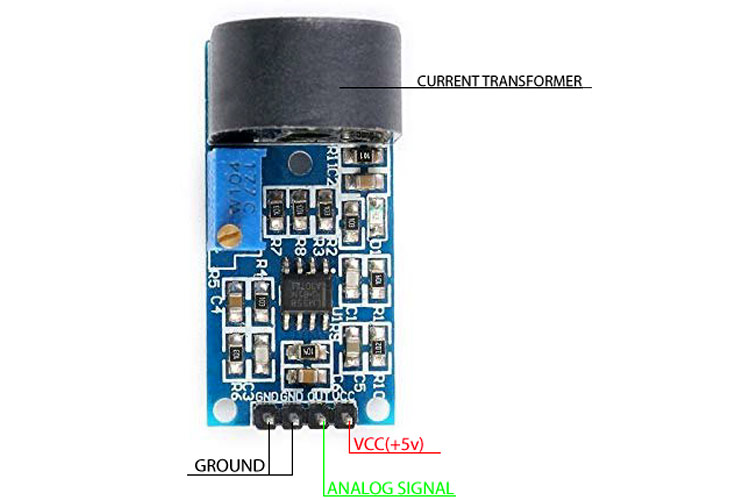
Pin Configuration and Descriptions

Pin Number Name Description
1 OUT Analog output voltage
2 GND Ground connection
3 +V Supply voltage input

Usage Instructions

How to Use the Component in a Circuit

  1. Power Supply: Connect the +V pin to a DC power supply within the range of 5V to 30V.
  2. Ground Connection: Connect the GND pin to the ground of your circuit.
  3. Output Signal: Connect the OUT pin to an analog input of a microcontroller, such as an Arduino, to read the sensor's output voltage.

Important Considerations and Best Practices

  • Ensure that the AC current being measured does not exceed the sensor's maximum rating of 5A.
  • The output voltage is linearly proportional to the AC current. Calibration may be required for precise measurements.
  • Avoid placing the sensor near high magnetic fields to prevent interference.
  • Use twisted pair wires for the connections to reduce noise pickup.
  • Keep the sensor away from high-temperature sources to maintain accuracy.

Example Code for Arduino UNO

// ZMCT103C Current Sensor Example Code for Arduino UNO

const int sensorPin = A0; // Analog input pin connected to ZMCT103C OUT pin
float sensorValue = 0;    // Variable to store sensor value

void setup() {
  Serial.begin(9600); // Start serial communication at 9600 baud rate
}

void loop() {
  sensorValue = analogRead(sensorPin); // Read the sensor output
  float current = sensorValue * (5.0 / 1023.0) / 0.185; // Convert to current (A)
  
  Serial.print("Current: ");
  Serial.print(current, 3); // Print the current with 3 decimal places
  Serial.println(" A");
  
  delay(1000); // Wait for 1 second before reading again
}

Note: The conversion factor 0.185 is based on the sensor's typical output of 1V at 5A. This value may need to be adjusted for calibration.

Troubleshooting and FAQs

Common Issues Users Might Face

  • Inaccurate Readings: Ensure proper calibration and that the sensor is not subjected to external magnetic fields.
  • No Output Voltage: Check the power supply connections and ensure the AC current is within the measurable range.
  • Sensor Overheating: Make sure the current does not exceed the sensor's maximum rating and that there is adequate ventilation.

Solutions and Tips for Troubleshooting

  • Calibration: Use a known current source to calibrate the sensor's output.
  • Wiring: Verify all connections are secure and free from shorts or opens.
  • Environment: Install the sensor in a location with minimal electrical noise and away from heat sources.

FAQs

Q: Can the ZMCT103C measure DC current? A: No, the ZMCT103C is designed to measure AC current only.

Q: What is the sensitivity of the sensor? A: The sensor has a sensitivity of approximately 0.185V/A, meaning for every ampere of current, the output voltage increases by 0.185V.

Q: How can I improve the accuracy of my measurements? A: For improved accuracy, calibrate the sensor with a known current source and ensure that the analog-to-digital conversion in your microcontroller is accurate.

Q: Is it necessary to use a burden resistor with this sensor? A: No, the ZMCT103C has a built-in burden resistor, so an external one is not required.

Q: Can I use this sensor with a 3.3V microcontroller? A: Yes, but you will need to scale the output voltage accordingly, as the sensor's output is designed for a 5V ADC reference.