How to Use SI5351: Examples, Pinouts, and Specs
Introduction
The SI5351 is a highly versatile programmable clock generator capable of producing multiple output frequencies with high precision. It is designed to generate clock signals for a wide range of applications, including communication systems, signal processing, microcontroller-based projects, and frequency synthesis. The SI5351 is particularly valued for its ability to generate stable and accurate timing signals, making it a popular choice in both hobbyist and professional electronics projects.
Explore Projects Built with SI5351


Explore Projects Built with SI5351
Common Applications
- Communication systems (e.g., RF transceivers)
- Signal processing and frequency synthesis
- Microcontroller clock generation
- Test and measurement equipment
- Amateur radio projects
Technical Specifications
The SI5351 is available in different variants (e.g., SI5351A, SI5351B, SI5351C), but the most commonly used version is the SI5351A. Below are the key technical specifications for the SI5351A:
Key Specifications
- Input Voltage (VDD): 2.5V to 3.3V
- Logic Level Voltage (VIO): 1.8V to 3.3V
- Frequency Range:
- Output: 8 kHz to 160 MHz
- Input Reference: 25 MHz or 27 MHz crystal
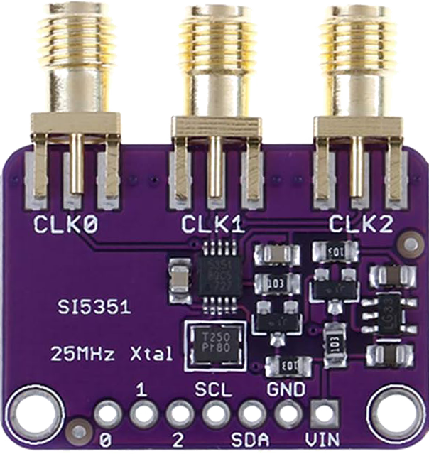
- Output Types: 3 independent clock outputs (CLK0, CLK1, CLK2)
- Output Drive Strength: Configurable (2 mA, 4 mA, 6 mA, 8 mA)
- Frequency Accuracy: ±20 ppm (with a high-quality crystal)
- Communication Interface: I²C (up to 400 kHz)
- Package: 10-pin MSOP or 10-pin QFN
Pin Configuration
The SI5351 has 10 pins, and their functions are described in the table below:
| Pin | Name | Description |
|---|---|---|
| 1 | VDD | Power supply input (2.5V to 3.3V). |
| 2 | GND | Ground connection. |
| 3 | CLK0 | Clock output 0. Configurable frequency. |
| 4 | CLK1 | Clock output 1. Configurable frequency. |
| 5 | CLK2 | Clock output 2. Configurable frequency. |
| 6 | SCL | I²C clock line. Used for communication with the microcontroller. |
| 7 | SDA | I²C data line. Used for communication with the microcontroller. |
| 8 | XTAL_IN | Input for external crystal (25 MHz or 27 MHz). |
| 9 | XTAL_OUT | Output for external crystal. |
| 10 | VIO | I²C interface voltage level (1.8V to 3.3V). |
Usage Instructions
How to Use the SI5351 in a Circuit
Power Supply:
- Connect the VDD pin to a 3.3V power source.
- Connect the GND pin to the ground of the circuit.
- Ensure the VIO pin matches the logic level of your microcontroller (e.g., 3.3V for most systems).
Crystal Oscillator:
- Connect a 25 MHz or 27 MHz crystal between the XTAL_IN and XTAL_OUT pins.
- Add two 18-22 pF capacitors between each crystal pin and ground for proper operation.
I²C Communication:
- Connect the SDA and SCL pins to the corresponding I²C pins on your microcontroller.
- Use pull-up resistors (typically 4.7 kΩ) on the SDA and SCL lines.
Clock Outputs:
- Connect the CLK0, CLK1, and/or CLK2 pins to the devices requiring clock signals.
- Configure the output frequencies via I²C commands.
Best Practices
- Use a high-quality crystal oscillator to ensure frequency stability and accuracy.
- Keep the I²C lines as short as possible to minimize noise and ensure reliable communication.
- Decouple the power supply with a 0.1 µF ceramic capacitor placed close to the VDD pin.
Example: Using the SI5351 with Arduino UNO
Below is an example of how to configure the SI5351 to generate a 10 MHz clock signal on CLK0 using an Arduino UNO:
#include <Wire.h>
#include <Adafruit_SI5351.h>

// Create an instance of the SI5351 library
Adafruit_SI5351 si5351;

void setup() {
  Serial.begin(9600); // Initialize serial communication for debugging

  // Initialize the SI5351
  if (!si5351.begin()) {
    Serial.println("SI5351 initialization failed!");
    while (1); // Halt if initialization fails
  }
  Serial.println("SI5351 initialized successfully.");

  // Set CLK0 to 10 MHz
  if (!si5351.setupPLL(SI5351_PLL_A, 900, 0, 1)) {
    Serial.println("Failed to configure PLL A.");
  }
  if (!si5351.setupMultisynth(0, SI5351_PLL_A, 90, 0, 1)) {
    Serial.println("Failed to configure Multisynth for CLK0.");
  }
  si5351.enableOutputs(true); // Enable all clock outputs
}

void loop() {
  // The SI5351 runs independently once configured, so no code is needed here
}
Notes:
- The Adafruit_SI5351 library is used in this example. Install it via the Arduino Library Manager.
- The
setupPLLandsetupMultisynthfunctions configure the internal PLL and clock dividers to generate the desired frequency.
Troubleshooting and FAQs
Common Issues
No Output Signal:
- Ensure the SI5351 is properly powered (check VDD and GND connections).
- Verify that the crystal oscillator is correctly connected and functioning.
- Check the I²C connections and ensure pull-up resistors are present.
Incorrect Output Frequency:
- Double-check the configuration of the PLL and multisynth dividers.
- Ensure the correct crystal frequency (25 MHz or 27 MHz) is specified in the code.
I²C Communication Failure:
- Verify the SDA and SCL connections to the microcontroller.
- Ensure the I²C address of the SI5351 matches the address used in the code (default: 0x60).
- Check for noise or interference on the I²C lines.
FAQs
Q: Can the SI5351 generate multiple frequencies simultaneously?
A: Yes, the SI5351 can generate up to three independent frequencies on CLK0, CLK1, and CLK2.
Q: What is the maximum output frequency of the SI5351?
A: The SI5351 can generate frequencies up to 160 MHz.
Q: Can I use the SI5351 with a 5V microcontroller?
A: Yes, but you must use a level shifter to convert the 5V I²C signals to 3.3V.
Q: How accurate are the output frequencies?
A: The accuracy depends on the quality of the crystal oscillator. With a ±20 ppm crystal, the output frequency will have a similar accuracy.
Q: Is the SI5351 suitable for RF applications?
A: Yes, the SI5351 is commonly used in RF applications, such as amateur radio, due to its high precision and stability.