How to Use 24/12v Buck: Examples, Pinouts, and Specs
Introduction
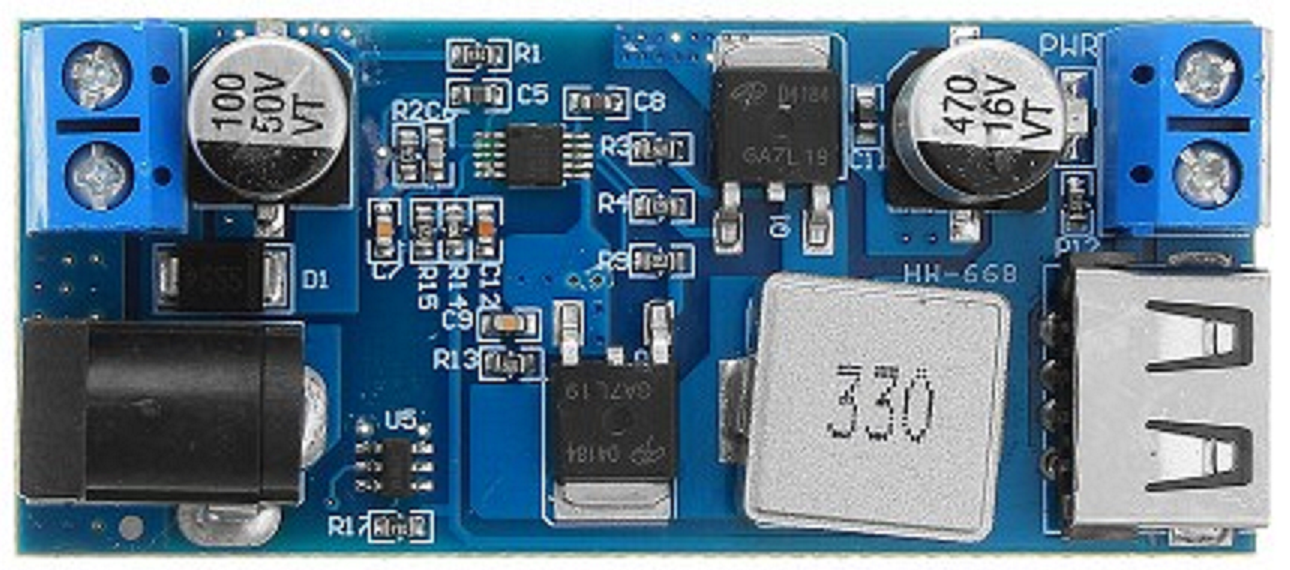
The 24/12V Buck Converter is a DC-DC step-down voltage regulator designed to efficiently convert a 24V input to a stable 12V output. This component is widely used in applications where a lower voltage is required to power devices from a higher voltage source. Its high efficiency ensures minimal power loss, making it ideal for battery-powered systems, automotive electronics, industrial equipment, and embedded systems.
Explore Projects Built with 24/12v Buck


Explore Projects Built with 24/12v Buck
Common Applications
- Powering 12V devices from a 24V battery or power supply
- Automotive systems (e.g., stepping down truck battery voltage)
- Industrial control systems
- Embedded systems and microcontroller projects
- LED lighting systems
Technical Specifications
The following table outlines the key technical details of the 24/12V Buck Converter:
| Parameter | Value |
|---|---|
| Input Voltage Range | 18V to 26V |
| Output Voltage | 12V ± 0.5V |
| Maximum Output Current | 5A |
| Efficiency | Up to 95% |
| Switching Frequency | 150 kHz |
| Operating Temperature | -40°C to +85°C |
| Dimensions | 45mm x 25mm x 15mm |
Pin Configuration and Descriptions
The 24/12V Buck Converter typically has four pins or terminals. The table below describes each pin:
| Pin/Terminal | Label | Description |
|---|---|---|
| 1 | VIN | Input voltage (connect to 24V power source) |
| 2 | GND | Ground (common ground for input and output) |
| 3 | VOUT | Output voltage (provides 12V regulated output) |
| 4 | EN (optional) | Enable pin (used to turn the converter on/off) |
Usage Instructions
How to Use the 24/12V Buck Converter in a Circuit
- Connect the Input Voltage:
- Connect the VIN pin to a 24V DC power source.
- Ensure the input voltage is within the specified range (18V to 26V) to avoid damage.
- Connect the Ground:
- Connect the GND pin to the ground of your circuit.
- Connect the Output Voltage:
- Connect the VOUT pin to the load that requires 12V.
- Ensure the load does not exceed the maximum output current of 5A.
- Optional Enable Pin:
- If the EN pin is available, connect it to a logic HIGH (e.g., 3.3V or 5V) to enable the converter. Leave it unconnected or pull it LOW to disable the converter.
Important Considerations and Best Practices
- Heat Dissipation: The converter may generate heat during operation, especially at high currents. Use a heatsink or ensure proper ventilation to prevent overheating.
- Input Voltage Protection: Use a fuse or transient voltage suppressor (TVS) diode on the input to protect the converter from voltage spikes.
- Output Filtering: For sensitive applications, consider adding a capacitor (e.g., 100µF) across the output to reduce noise and ripple.
- Polarity: Double-check the polarity of the input and output connections to avoid damage to the converter or connected devices.
Example: Using the 24/12V Buck Converter with an Arduino UNO
The 24/12V Buck Converter can be used to power an Arduino UNO from a 24V power source. Below is an example circuit and code:
Circuit Connections
- Connect the VIN pin of the buck converter to the 24V power source.
- Connect the GND pin of the buck converter to the ground of the power source and the Arduino.
- Connect the VOUT pin of the buck converter to the Arduino's VIN pin.
Arduino Code Example
// Example code to blink an LED connected to pin 13 of the Arduino UNO
// Ensure the Arduino is powered via the 24/12V Buck Converter

void setup() {
  pinMode(13, OUTPUT); // Set pin 13 as an output
}

void loop() {
  digitalWrite(13, HIGH); // Turn the LED on
  delay(1000);            // Wait for 1 second
  digitalWrite(13, LOW);  // Turn the LED off
  delay(1000);            // Wait for 1 second
}
Troubleshooting and FAQs
Common Issues and Solutions
No Output Voltage:
- Check the input voltage to ensure it is within the specified range (18V to 26V).
- Verify that the EN pin is connected to a logic HIGH (if applicable).
- Inspect the connections for loose wires or incorrect polarity.
Overheating:
- Ensure the load current does not exceed the maximum rating of 5A.
- Improve ventilation or attach a heatsink to the converter.
Output Voltage Fluctuations:
- Add a capacitor (e.g., 100µF) across the output to stabilize the voltage.
- Check for noise or instability in the input power source.
Damaged Converter:
- Verify that the input voltage polarity is correct.
- Ensure the input voltage does not exceed 26V.
FAQs
Q: Can I use the 24/12V Buck Converter to power multiple devices?
A: Yes, as long as the total current draw does not exceed the maximum output current of 5A.
Q: What happens if the input voltage drops below 18V?
A: The converter may fail to regulate the output voltage properly, leading to instability or a complete loss of output.
Q: Is the converter suitable for automotive applications?
A: Yes, the 24/12V Buck Converter is commonly used in automotive systems to step down truck or bus battery voltage to 12V.
Q: Can I adjust the output voltage?
A: Most 24/12V Buck Converters have a fixed output voltage. If adjustable output is required, look for a model with a potentiometer or adjustment feature.