How to Use stepper motor driver board: Examples, Pinouts, and Specs

Introduction
A stepper motor driver board is a crucial electronic device designed to control the precise movement of a stepper motor, which is a type of electric motor that moves in discrete steps. The driver board sends signals to the motor, enabling it to rotate in fixed angles and hold its position without a feedback system. This makes stepper motors ideal for applications requiring controlled, repeatable movements such as 3D printers, CNC machines, and robotics.
Explore Projects Built with stepper motor driver board

Explore Projects Built with stepper motor driver board
Technical Specifications
General Features
- Control Interface: Digital I/O compatible
- Input Voltage: Typically 8V to 35V (varies by model)
- Output Current: Up to 2A per channel (varies by model)
- Microstepping: Full, 1/2, 1/4, 1/8, 1/16 step (varies by model)
- Protection: Overcurrent, thermal, under-voltage lockout
Pin Configuration and Descriptions
| Pin Number | Name | Description |
|---|---|---|
| 1 | VDD | Logic supply voltage (5V typical) |
| 2 | GND | Ground connection |
| 3 | 2B | Motor coil B output 2 |
| 4 | 2A | Motor coil A output 2 |
| 5 | 1A | Motor coil A output 1 |
| 6 | 1B | Motor coil B output 1 |
| 7 | EN | Enable input (active low) |
| 8 | MS1 | Microstep select 1 |
| 9 | MS2 | Microstep select 2 |
| 10 | MS3 | Microstep select 3 |
| 11 | RST | Reset input (active low) |
| 12 | SLP | Sleep mode input (active low) |
| 13 | STEP | Step input |
| 14 | DIR | Direction input |
Usage Instructions
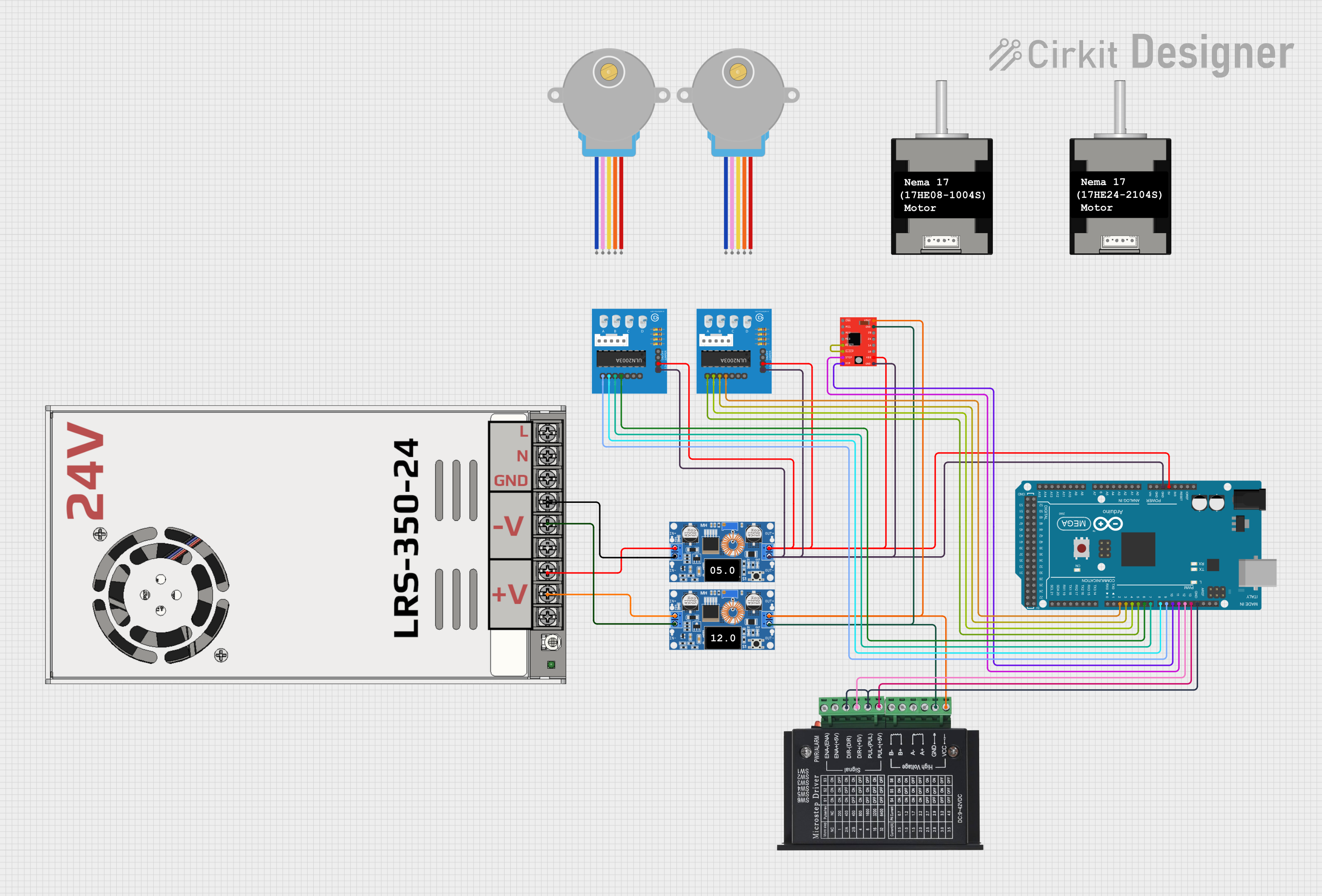
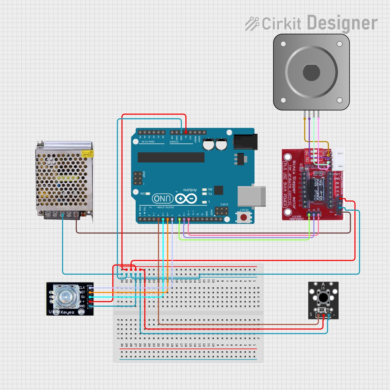
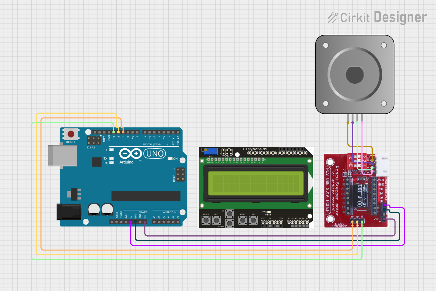
Connecting the Driver to a Stepper Motor
- Power Supply: Connect a suitable power supply to the motor power inputs, ensuring the voltage is within the specified range for your driver board.
- Motor Connections: Connect the stepper motor coils to the driver board's motor output pins. It is essential to refer to the motor's datasheet to identify the correct wiring configuration.
- Control Signals: Connect the control inputs (STEP, DIR, EN, etc.) to your microcontroller or control system.
- Microstepping Configuration: Set the microstepping resolution by configuring the MS1, MS2, and MS3 pins according to the desired step size.
Best Practices
- Always disconnect the power before making or changing connections.
- Use a heatsink if the driver operates at high currents to prevent overheating.
- Ensure that the current limit is set correctly to prevent damage to the motor or driver.
- Avoid running the motor at its maximum rated current for extended periods.
Example Code for Arduino UNO
// Define the stepper motor control pins
#define DIR_PIN 2
#define STEP_PIN 3
#define ENABLE_PIN 4

void setup() {
  // Set the control pins as outputs
  pinMode(DIR_PIN, OUTPUT);
  pinMode(STEP_PIN, OUTPUT);
  pinMode(ENABLE_PIN, OUTPUT);

  // Enable the stepper motor driver
  digitalWrite(ENABLE_PIN, LOW);
}

void loop() {
  // Set the direction of the motor
  digitalWrite(DIR_PIN, HIGH); // Set to LOW to change direction

  // Move the motor one step
  digitalWrite(STEP_PIN, HIGH);
  delayMicroseconds(1000); // Delay determines the speed
  digitalWrite(STEP_PIN, LOW);
  delayMicroseconds(1000);
}
Troubleshooting and FAQs
Common Issues
- Motor not moving: Check power supply, wiring, and ensure the enable pin is set correctly.
- Motor stalling or skipping steps: This may be due to excessive speed, high load, or incorrect current limit settings.
- Overheating: Ensure proper current settings and adequate cooling.
FAQs
Q: How do I set the current limit on my stepper motor driver? A: The current limit is typically set via a potentiometer on the driver board. Consult the specific driver board's datasheet for instructions.
Q: Can I run the stepper motor at a higher voltage than rated? A: Operating at a higher voltage can lead to increased performance but must not exceed the driver board's maximum voltage rating.
Q: What is microstepping and how do I use it? A: Microstepping divides a full step into smaller steps for smoother motion. Use the MS1, MS2, and MS3 pins to configure the microstepping resolution.
For further assistance, consult the manufacturer's datasheet and technical support resources.