
How to Use Power Distribution Board: Examples, Pinouts, and Specs
 Design with Power Distribution Board in Cirkit Designer
Introduction
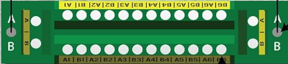
A Power Distribution Board (PDB) is a crucial electronic component designed to distribute electrical power efficiently to various components in a system. It ensures that each connected device receives the appropriate voltage and current, enabling stable and reliable operation. PDBs are commonly used in applications such as drones, robotics, RC vehicles, and other systems requiring multiple power outputs. Many PDBs also include built-in safety features like fuses or circuit breakers to protect against overcurrent or short circuits.
Explore Projects Built with Power Distribution Board
 Open Project in Cirkit Designer
 Open Project in Cirkit Designer
 Open Project in Cirkit Designer
 Open Project in Cirkit Designer
Explore Projects Built with Power Distribution Board
Open Project in Cirkit DesignerOpen Project in Cirkit DesignerOpen Project in Cirkit DesignerOpen Project in Cirkit DesignerCommon Applications and Use Cases
- Powering multiple motors and electronic speed controllers (ESCs) in drones and RC vehicles.
- Distributing power to sensors, microcontrollers, and actuators in robotics.
- Providing regulated power to various modules in embedded systems.
- Simplifying wiring in complex circuits by centralizing power distribution.
Technical Specifications
Below are the general technical specifications for a typical Power Distribution Board. Note that specific models may vary, so always refer to the datasheet of your PDB for exact details.
Key Technical Details
- Input Voltage Range: 7V to 26V (2S to 6S LiPo batteries)
- Maximum Current: 100A (total), 20A per output (varies by model)
- Number of Outputs: 4 to 8 (depending on the design)
- Built-in Protection: Overcurrent protection, short-circuit protection, and reverse polarity protection (if available)
- Connector Types: XT60, XT90, solder pads, or screw terminals
- Dimensions: Typically 36mm x 36mm to 50mm x 50mm
- Weight: 10g to 30g
Pin Configuration and Descriptions
The following table outlines the typical pin or connector configuration for a Power Distribution Board:
| Pin/Connector | Description |
|---|---|
| Input (+) | Positive terminal for the main power input (e.g., from a LiPo battery). |
| Input (-) | Negative terminal for the main power input (ground). |
| Output (+) | Positive terminal for distributing power to connected components. |
| Output (-) | Negative terminal for distributing power to connected components (ground). |
| Voltage Regulator | Optional output providing regulated voltage (e.g., 5V or 12V) for peripherals. |
| Fuse Holder | Slot for fuses to protect individual outputs (if applicable). |
Usage Instructions
How to Use the Component in a Circuit
- Connect the Power Source:
- Attach the positive and negative terminals of your power source (e.g., a LiPo battery) to the PDB's input connectors. Ensure the polarity is correct to avoid damage.
- Connect the Outputs:
- Solder or plug in the wires for each component (e.g., motors, ESCs, or sensors) to the corresponding output terminals on the PDB.
- Secure the Board:
- Mount the PDB securely in your system using screws, standoffs, or adhesive to prevent movement during operation.
- Check Connections:
- Verify all connections are secure and that there are no exposed wires that could cause a short circuit.
- Power On:
- Turn on the power source and monitor the system for any irregularities, such as overheating or unexpected behavior.
Important Considerations and Best Practices
- Match Voltage and Current Ratings: Ensure the PDB's input voltage and current ratings match your power source and connected components.
- Use Fuses: If your PDB supports fuses, install them to protect against overcurrent conditions.
- Avoid Overloading: Do not exceed the maximum current rating for individual outputs or the total current rating of the PDB.
- Heat Dissipation: If the PDB operates at high currents, ensure adequate ventilation or cooling to prevent overheating.
- Polarity Check: Double-check the polarity of all connections to avoid damaging the board or connected devices.
Example: Connecting a PDB to an Arduino UNO
If you are using a PDB to power an Arduino UNO and other peripherals, follow these steps:
- Connect the PDB's regulated 5V output to the Arduino's 5V pin.
- Connect the PDB's ground (GND) to the Arduino's GND pin.
- Use the remaining PDB outputs to power other components, such as sensors or actuators.
Here is an example Arduino code to control a motor powered via the PDB:
// Example code to control a motor using Arduino UNO
// Ensure the motor is powered via the PDB and connected to a motor driver

const int motorPin = 9; // PWM pin connected to the motor driver

void setup() {
  pinMode(motorPin, OUTPUT); // Set motor pin as output
}

void loop() {
  analogWrite(motorPin, 128); // Set motor speed to 50% (PWM value: 128 out of 255)
  delay(2000);               // Run motor for 2 seconds
  analogWrite(motorPin, 0);   // Stop motor
  delay(2000);               // Wait for 2 seconds
}
Troubleshooting and FAQs
Common Issues Users Might Face
PDB Overheating:
- Cause: Exceeding the maximum current rating or poor ventilation.
- Solution: Reduce the load on the PDB or improve airflow around the board.
No Power to Outputs:
- Cause: Loose connections, blown fuses, or incorrect polarity.
- Solution: Check all connections, replace blown fuses, and verify polarity.
Short Circuit:
- Cause: Exposed wires or solder bridges on the PDB.
- Solution: Inspect the board for shorts and correct any issues.
Voltage Drop:
- Cause: High current draw or inadequate power source.
- Solution: Use a power source with sufficient capacity and minimize resistance in wiring.
Solutions and Tips for Troubleshooting
- Use a multimeter to check voltage levels at the input and output terminals.
- Inspect the PDB for physical damage, such as burnt components or broken traces.
- If the PDB includes LEDs for status indication, refer to the user manual to interpret their signals.
- Always disconnect the power source before making adjustments to the circuit.
By following this documentation, you can effectively integrate and troubleshoot a Power Distribution Board in your electronic projects.