Cirkit Designer
Your all-in-one circuit design IDE
Home /
Component Documentation
How to Use Humiture Sensor: Examples, Pinouts, and Specs
Introduction
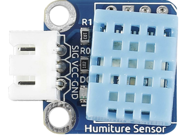
The Humiture Sensor by SunFounder (Part ID: Humiture Sensor) is a versatile device designed to measure both humidity and temperature. This sensor is commonly used in environmental monitoring, HVAC systems, weather stations, and various IoT applications. Its ability to provide accurate and reliable data makes it an essential component for projects that require precise environmental measurements.
Explore Projects Built with Humiture Sensor
Arduino UNO Based IoT Indoor Air Quality Monitor with WiFi Connectivity
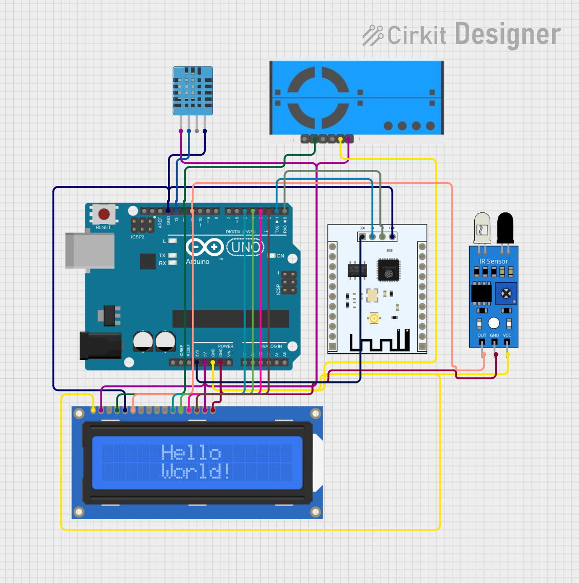
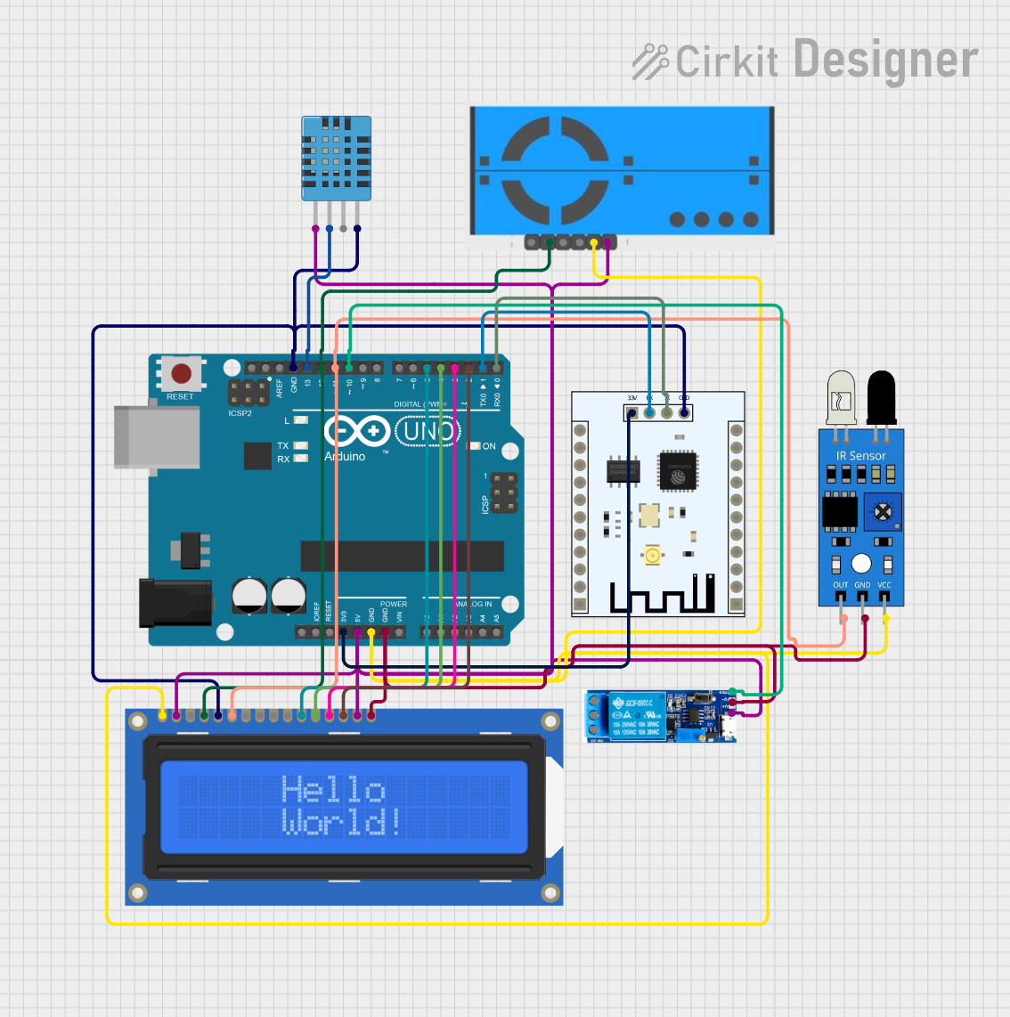
This circuit is designed for an IoT-based indoor air quality monitoring system named IHIP (Integrated Humidity, Infrared, and Particulates System). It utilizes an Arduino UNO to interface with a DHT11 humidity and temperature sensor, a PM2.5 air quality sensor, an IR sensor, and an ESP8266 WiFi module for data communication. The system reads environmental data and displays it on a 16x2 LCD screen while also sending the data to a remote server or service via the WiFi module for monitoring purposes.
ESP32-Based Smart Humidity and Temperature Controller with Wi-Fi Connectivity
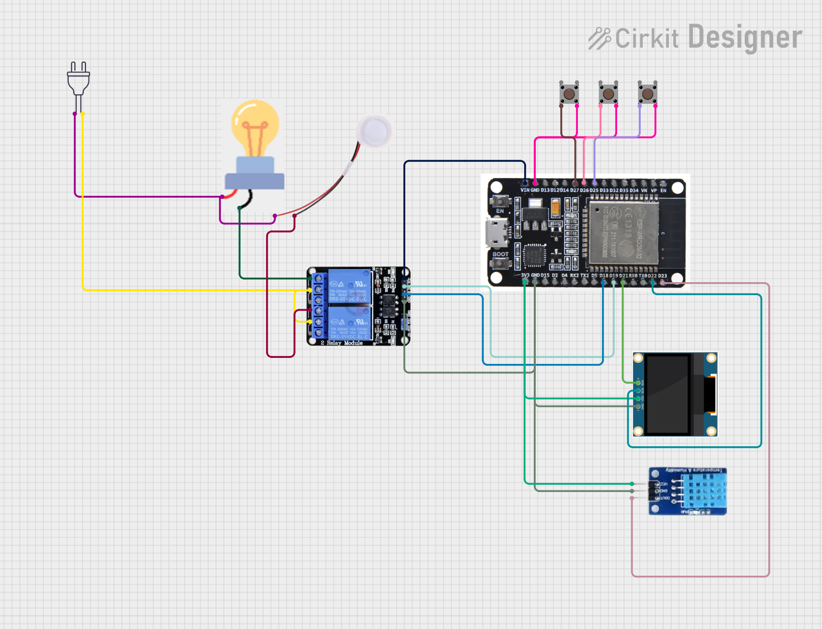
This circuit is designed to monitor and control temperature and humidity using an ESP32 microcontroller, which interfaces with a DHT11 sensor, an OLED display, and a two-channel relay. The ESP32 uses Blynk for IoT connectivity, allowing remote monitoring and control of a connected humidifier and a bulb (as a heater). Pushbuttons are included for manual control, and the system operates in either automatic or manual mode to maintain desired environmental conditions.
Air Quality and Humidity Monitoring System with NodeMCU and I2C LCD Display
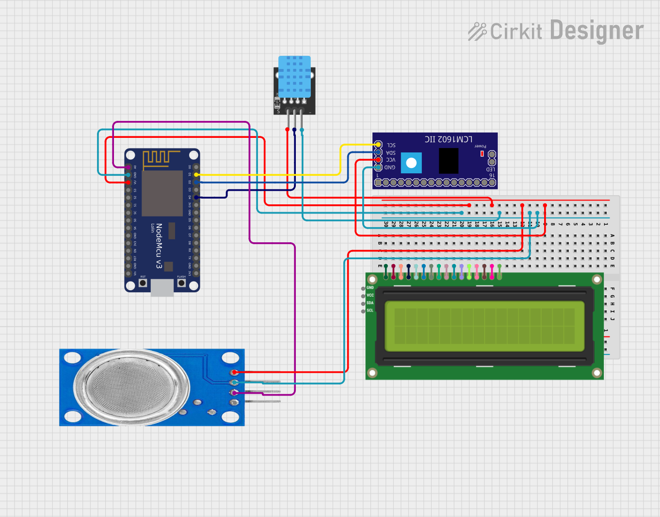
This circuit is designed for real-time air quality and humidity monitoring. It uses an MQ135 sensor to measure air quality, a DHT11 sensor to measure temperature and humidity, and displays the readings on an I2C LCD 16x2 screen. The NodeMCU V3 ESP8266 microcontroller processes the sensor data and controls the display output.
Arduino UNO-Based IoT Indoor Air Quality Monitoring System with Wi-Fi and LCD Display
This circuit is an IoT-based indoor air quality monitoring and control system. It uses an Arduino UNO to read data from a DHT11 humidity and temperature sensor, an IR sensor, and a PM2.5 air quality sensor, displaying the data on an LCD and sending it to an ESP8266 WiFi module for remote monitoring. Additionally, the system controls a relay based on the sensor readings.
Explore Projects Built with Humiture Sensor
Arduino UNO Based IoT Indoor Air Quality Monitor with WiFi Connectivity
This circuit is designed for an IoT-based indoor air quality monitoring system named IHIP (Integrated Humidity, Infrared, and Particulates System). It utilizes an Arduino UNO to interface with a DHT11 humidity and temperature sensor, a PM2.5 air quality sensor, an IR sensor, and an ESP8266 WiFi module for data communication. The system reads environmental data and displays it on a 16x2 LCD screen while also sending the data to a remote server or service via the WiFi module for monitoring purposes.
ESP32-Based Smart Humidity and Temperature Controller with Wi-Fi Connectivity
This circuit is designed to monitor and control temperature and humidity using an ESP32 microcontroller, which interfaces with a DHT11 sensor, an OLED display, and a two-channel relay. The ESP32 uses Blynk for IoT connectivity, allowing remote monitoring and control of a connected humidifier and a bulb (as a heater). Pushbuttons are included for manual control, and the system operates in either automatic or manual mode to maintain desired environmental conditions.
Air Quality and Humidity Monitoring System with NodeMCU and I2C LCD Display
This circuit is designed for real-time air quality and humidity monitoring. It uses an MQ135 sensor to measure air quality, a DHT11 sensor to measure temperature and humidity, and displays the readings on an I2C LCD 16x2 screen. The NodeMCU V3 ESP8266 microcontroller processes the sensor data and controls the display output.
Arduino UNO-Based IoT Indoor Air Quality Monitoring System with Wi-Fi and LCD Display
This circuit is an IoT-based indoor air quality monitoring and control system. It uses an Arduino UNO to read data from a DHT11 humidity and temperature sensor, an IR sensor, and a PM2.5 air quality sensor, displaying the data on an LCD and sending it to an ESP8266 WiFi module for remote monitoring. Additionally, the system controls a relay based on the sensor readings.
Technical Specifications
Key Technical Details
| Parameter | Value |
|---|---|
| Operating Voltage | 3.3V - 5V |
| Humidity Range | 0% - 100% RH |
| Temperature Range | -40°C to 80°C |
| Humidity Accuracy | ±2% RH |
| Temperature Accuracy | ±0.5°C |
| Interface | Digital (Single-Wire) |
| Response Time | < 2 seconds |
| Dimensions | 15mm x 12mm x 5mm |
Pin Configuration and Descriptions
| Pin Number | Pin Name | Description |
|---|---|---|
| 1 | VCC | Power supply (3.3V - 5V) |
| 2 | DATA | Data signal (Digital) |
| 3 | NC | Not connected |
| 4 | GND | Ground |
Usage Instructions
How to Use the Component in a Circuit
- Power Supply: Connect the VCC pin to a 3.3V or 5V power supply.
- Ground: Connect the GND pin to the ground of your circuit.
- Data Signal: Connect the DATA pin to a digital input pin on your microcontroller (e.g., Arduino UNO).
Important Considerations and Best Practices
- Power Supply: Ensure that the power supply voltage is within the specified range (3.3V - 5V) to avoid damaging the sensor.
- Data Line: Use a pull-up resistor (typically 10kΩ) on the DATA line to ensure reliable communication.
- Environmental Factors: Place the sensor in a location where it can accurately measure the ambient temperature and humidity without obstruction.
- Calibration: Periodically calibrate the sensor to maintain accuracy, especially in critical applications.
Sample Arduino Code
Below is a sample code to interface the Humiture Sensor with an Arduino UNO:
#include <DHT.h>

// Define the pin where the DATA line is connected
#define DHTPIN 2

// Define the type of sensor (DHT11, DHT22, etc.)
#define DHTTYPE DHT11

// Initialize the DHT sensor
DHT dht(DHTPIN, DHTTYPE);

void setup() {
  // Start the serial communication
  Serial.begin(9600);
  // Initialize the sensor
  dht.begin();
}

void loop() {
  // Wait a few seconds between measurements
  delay(2000);

  // Read humidity
  float humidity = dht.readHumidity();
  // Read temperature in Celsius
  float temperature = dht.readTemperature();

  // Check if any reads failed and exit early (to try again)
  if (isnan(humidity) || isnan(temperature)) {
    Serial.println("Failed to read from DHT sensor!");
    return;
  }

  // Print the results to the Serial Monitor
  Serial.print("Humidity: ");
  Serial.print(humidity);
  Serial.print(" %\t");
  Serial.print("Temperature: ");
  Serial.print(temperature);
  Serial.println(" *C");
}
Troubleshooting and FAQs
Common Issues Users Might Face
- No Data Output: Ensure that the sensor is properly connected and that the DATA pin is connected to the correct digital input pin on the microcontroller.
- Incorrect Readings: Verify that the sensor is placed in an appropriate location and that there are no obstructions affecting the measurements.
- Communication Errors: Check the pull-up resistor on the DATA line and ensure it is correctly connected.
Solutions and Tips for Troubleshooting
- Check Connections: Double-check all connections to ensure they are secure and correctly placed.
- Verify Code: Ensure that the correct pin number and sensor type are defined in the code.
- Power Supply: Make sure the sensor is receiving the correct voltage.
- Sensor Placement: Place the sensor in a stable environment to avoid fluctuations in readings.
By following this documentation, users can effectively integrate the SunFounder Humiture Sensor into their projects, ensuring accurate and reliable environmental measurements.