How to Use SCT013 30A/1V: Examples, Pinouts, and Specs
Introduction
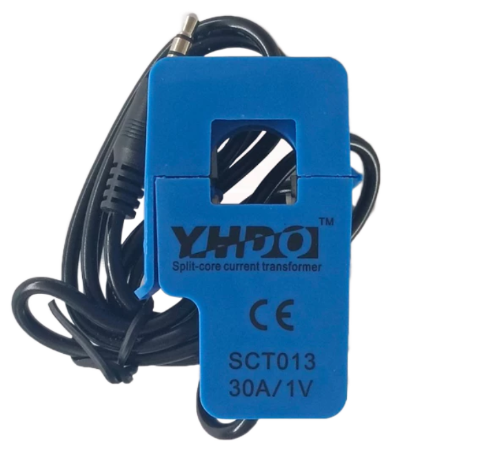
The SCT013 30A/1V is a non-invasive current transformer designed for measuring alternating current (AC). It is widely used in energy monitoring systems to measure current without requiring direct electrical contact with the conductor. The device outputs a voltage signal proportional to the current flowing through the conductor, with a maximum output of 1 volt when the primary current reaches 30 amps.
Explore Projects Built with SCT013 30A/1V


Explore Projects Built with SCT013 30A/1V
Common Applications and Use Cases
- Energy monitoring in residential, commercial, and industrial settings
- Smart home energy management systems
- Load analysis and power consumption tracking
- Non-invasive current measurement for safety-critical applications
Technical Specifications
Below are the key technical details of the SCT013 30A/1V current transformer:
| Parameter | Value |
|---|---|
| Model | SCT013 30A/1V |
| Maximum Primary Current | 30 A |
| Output Voltage | 1 V (at 30 A primary current) |
| Core Material | Ferrite |
| Accuracy Class | ±1% |
| Operating Frequency | 50 Hz - 1 kHz |
| Internal Burden Resistor | Yes |
| Cable Length | 1 meter |
| Output Connector | 3.5 mm audio jack |
Pin Configuration and Descriptions
The SCT013 30A/1V has a simple interface with the following connections:
| Pin/Connection | Description |
|---|---|
| Tip (3.5 mm Jack) | Positive voltage output proportional to the measured current |
| Sleeve (3.5 mm Jack) | Ground reference for the output signal |
Usage Instructions
How to Use the SCT013 30A/1V in a Circuit
Connect the Transformer:
- Clamp the SCT013 around the live or neutral wire of the AC circuit you want to measure. Ensure the wire is fully enclosed within the clamp for accurate readings.
- Plug the 3.5 mm audio jack into the input of your measurement device (e.g., an Arduino or energy monitoring module).
Add a Load Resistor (if needed):
- The SCT013 30A/1V includes an internal burden resistor, so no external resistor is required for standard applications. However, verify this based on your specific use case.
Interface with a Microcontroller:
- To measure the output voltage, connect the SCT013 to an analog input pin of a microcontroller (e.g., Arduino UNO). Use a voltage divider or signal conditioning circuit if necessary to ensure the input voltage is within the microcontroller's ADC range.
Calibrate the System:
- Use a known current source to calibrate the system and ensure accurate measurements. Adjust the calibration factor in your software accordingly.
Important Considerations and Best Practices
- Safety First: The SCT013 is designed for non-invasive current measurement. Do not attempt to measure current on live wires without proper insulation and safety precautions.
- Avoid Saturation: Ensure the measured current does not exceed 30 A, as this may saturate the transformer and result in inaccurate readings.
- Signal Filtering: For noisy environments, consider adding a low-pass filter to the output signal to improve measurement accuracy.
- Orientation: Pay attention to the orientation of the clamp. The arrow on the SCT013 should point in the direction of current flow for correct polarity.
Example Code for Arduino UNO
Below is an example of how to use the SCT013 30A/1V with an Arduino UNO to measure AC current:
// Include necessary libraries
const int sensorPin = A0;  // Analog pin connected to SCT013 output
const float calibrationFactor = 30.0; // Calibration factor for 30A/1V

void setup() {
  Serial.begin(9600); // Initialize serial communication
}

void loop() {
  int sensorValue = analogRead(sensorPin); // Read analog value from SCT013
  float voltage = (sensorValue / 1023.0) * 5.0; // Convert to voltage (5V ADC)

  // Calculate current using calibration factor
  float current = (voltage / 1.0) * calibrationFactor;

  // Print the measured current to the Serial Monitor
  Serial.print("Current: ");
  Serial.print(current);
  Serial.println(" A");

  delay(1000); // Wait 1 second before next reading
}
Troubleshooting and FAQs
Common Issues and Solutions
No Output Signal:
- Ensure the SCT013 is properly clamped around the conductor.
- Verify that the conductor is carrying AC current and not DC, as the SCT013 is designed for AC measurement only.
Inaccurate Readings:
- Check the calibration factor in your software. Use a known current source to recalibrate if necessary.
- Ensure the wire is centered within the clamp for optimal accuracy.
Noise in Output Signal:
- Add a capacitor (e.g., 10 µF) across the output to filter high-frequency noise.
- Use shielded cables or reduce the length of the output cable to minimize interference.
Saturation or Clipping:
- Ensure the measured current does not exceed 30 A. If higher currents are expected, consider using a higher-rated current transformer.
FAQs
Q: Can the SCT013 measure DC current?
A: No, the SCT013 is designed for AC current measurement only. It cannot measure DC current.
Q: Do I need an external burden resistor?
A: No, the SCT013 30A/1V includes an internal burden resistor. However, verify this for your specific model.
Q: Can I use the SCT013 with a Raspberry Pi?
A: Yes, but since the Raspberry Pi lacks an analog input, you will need an external ADC (Analog-to-Digital Converter) to interface the SCT013 with the Raspberry Pi.
Q: What happens if I reverse the clamp orientation?
A: Reversing the clamp orientation will invert the polarity of the output signal. Ensure the arrow on the clamp points in the direction of current flow for correct readings.