How to Use ir sensor : Examples, Pinouts, and Specs
Introduction
An infrared (IR) sensor detects infrared radiation, which is invisible to the human eye but can be emitted by objects as heat or light. IR sensors are widely used in various applications, including proximity sensing, motion detection, and remote control systems. These sensors are versatile and can be used in both analog and digital circuits, making them a popular choice for hobbyists and professionals alike.
Common applications of IR sensors include:
- Obstacle detection in robotics
- Line-following robots
- Motion detection for security systems
- Remote control signal reception
- Automatic door systems
Explore Projects Built with ir sensor
Explore Projects Built with ir sensor
Technical Specifications
Below are the key technical details of a typical IR sensor module:
| Parameter | Value |
|---|---|
| Operating Voltage | 3.3V to 5V |
| Operating Current | 20mA (typical) |
| Detection Range | 2cm to 30cm (varies by model) |
| Output Type | Digital (High/Low) or Analog |
| Wavelength | 760nm to 1100nm (infrared range) |
| Response Time | < 2ms |
| Operating Temperature | -25°C to 85°C |
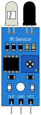
Pin Configuration
The IR sensor module typically has three or more pins. Below is the pin configuration for a common 3-pin IR sensor module:
| Pin | Name | Description |
|---|---|---|
| 1 | VCC | Power supply pin (3.3V to 5V) |
| 2 | GND | Ground pin |
| 3 | OUT | Output pin (Digital or Analog signal based on model) |
Usage Instructions
How to Use the IR Sensor in a Circuit
- Power the Sensor: Connect the VCC pin to a 3.3V or 5V power source and the GND pin to the ground of your circuit.
- Connect the Output: Connect the OUT pin to a microcontroller (e.g., Arduino) or any other processing unit to read the sensor's output.
- For digital IR sensors, the output will be HIGH (1) when no object is detected and LOW (0) when an object is detected (or vice versa, depending on the module).
- For analog IR sensors, the output voltage will vary based on the distance of the detected object.
- Adjust Sensitivity (if applicable): Some IR sensor modules have a potentiometer to adjust the detection range or sensitivity. Turn the potentiometer clockwise or counterclockwise to fine-tune the sensor's performance.
Important Considerations and Best Practices
- Avoid Ambient Light Interference: IR sensors can be affected by strong ambient light. Use them in controlled lighting conditions or shield the sensor from direct sunlight.
- Check the Detection Range: Ensure the sensor's range is suitable for your application. Some models may have limited range.
- Use Pull-Up Resistors (if needed): For digital output, you may need to use a pull-up resistor to stabilize the signal.
- Test Before Deployment: Test the sensor in your specific application to ensure reliable performance.
Example: Connecting an IR Sensor to an Arduino UNO
Below is an example of how to connect and use a digital IR sensor with an Arduino UNO:
Circuit Connections
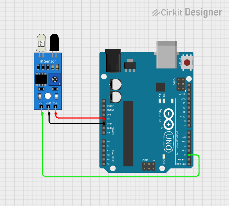
- Connect the VCC pin of the IR sensor to the 5V pin on the Arduino.
- Connect the GND pin of the IR sensor to the GND pin on the Arduino.
- Connect the OUT pin of the IR sensor to digital pin 2 on the Arduino.
Arduino Code
// IR Sensor Example Code
// This code reads the digital output of the IR sensor and prints the status
// to the Serial Monitor.

const int irSensorPin = 2; // IR sensor output connected to digital pin 2
int sensorValue = 0;       // Variable to store the sensor reading

void setup() {
  pinMode(irSensorPin, INPUT); // Set the IR sensor pin as input
  Serial.begin(9600);          // Initialize serial communication at 9600 baud
}

void loop() {
  sensorValue = digitalRead(irSensorPin); // Read the sensor output
  if (sensorValue == HIGH) {
    Serial.println("No object detected"); // Print message if no object is detected
  } else {
    Serial.println("Object detected");    // Print message if an object is detected
  }
  delay(100); // Small delay to avoid flooding the Serial Monitor
}
Troubleshooting and FAQs
Common Issues and Solutions
The sensor is not detecting objects:
- Ensure the sensor is powered correctly (check VCC and GND connections).
- Verify that the object is within the sensor's detection range.
- Adjust the sensitivity using the potentiometer (if available).
False detections or unstable output:
- Reduce ambient light interference by shielding the sensor.
- Check for electrical noise in the circuit and use decoupling capacitors if necessary.
Output signal is not readable by the microcontroller:
- Ensure the output pin is connected to the correct microcontroller pin.
- For analog sensors, ensure the microcontroller's ADC (Analog-to-Digital Converter) is configured correctly.
FAQs
Q: Can the IR sensor detect transparent objects?
A: IR sensors may struggle to detect transparent or highly reflective objects. Use specialized sensors for such applications.
Q: What is the maximum range of an IR sensor?
A: The range varies by model, typically between 2cm and 30cm. Check the datasheet for your specific sensor.
Q: Can I use an IR sensor outdoors?
A: Yes, but performance may be affected by sunlight or other IR sources. Use shielding or filters to improve reliability.
Q: How do I know if my IR sensor is working?
A: Test the sensor by placing an object within its range and observing the output signal. You can also use an LED or multimeter to verify the output.