
How to Use BASIC Stamp 2p24: Examples, Pinouts, and Specs
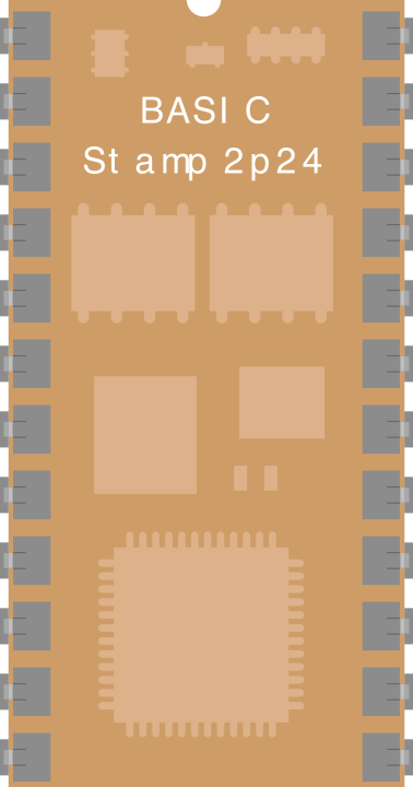
 Design with BASIC Stamp 2p24 in Cirkit Designer
Introduction
The BASIC Stamp 2p24 (Part ID: BS2p24-IC) is a microcontroller module manufactured by Parallax. It is designed for ease of use and versatility, making it an excellent choice for both beginners and experienced developers. The module is programmable in PBASIC, a simple yet powerful language, and comes in a 24-pin DIP package for straightforward integration into breadboards or custom PCBs.
The BASIC Stamp 2p24 is equipped with built-in I/O pins, a serial interface, and support for a wide range of sensors and actuators. It is commonly used in robotics, home automation, data acquisition, and educational projects.
Explore Projects Built with BASIC Stamp 2p24
 Open Project in Cirkit Designer
 Open Project in Cirkit Designer
 Open Project in Cirkit Designer
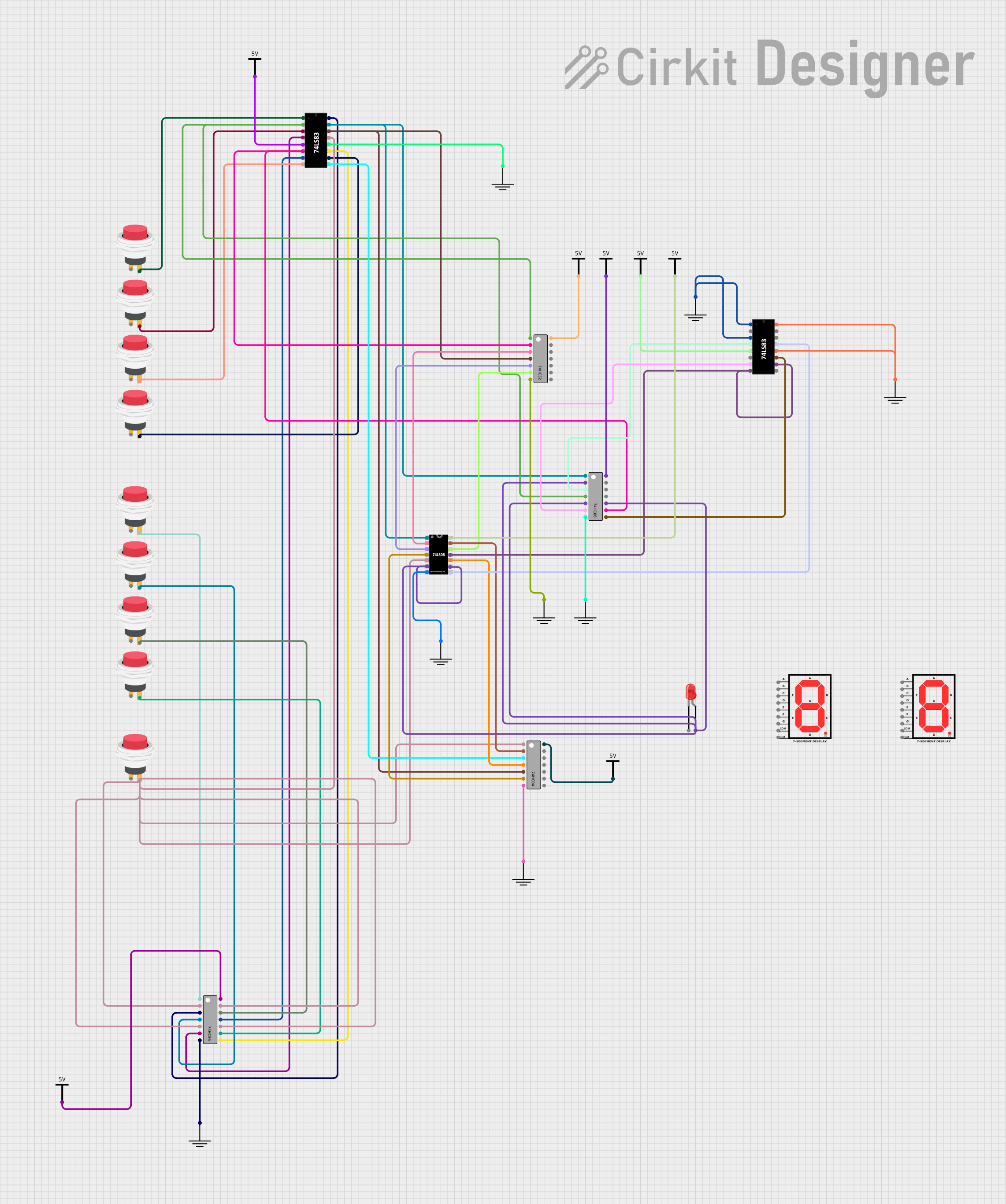 Open Project in Cirkit Designer
Explore Projects Built with BASIC Stamp 2p24
Open Project in Cirkit DesignerOpen Project in Cirkit DesignerOpen Project in Cirkit DesignerOpen Project in Cirkit DesignerTechnical Specifications
Key Technical Details
- Microcontroller: Parallax PBASIC Interpreter Chip
- Operating Voltage: 5 V DC
- Current Consumption: 3 mA (running), 50 µA (sleep mode)
- Clock Speed: 20 MHz
- Program Memory: 2 KB EEPROM (up to 4,000 PBASIC instructions)
- RAM: 38 bytes
- I/O Pins: 16 (TTL-compatible)
- Communication: Serial (RS-232 or USB via adapter)
- Package: 24-pin DIP
- Dimensions: 1.2" x 0.6" (30.5 mm x 15.2 mm)
Pin Configuration and Descriptions
The BASIC Stamp 2p24 has a 24-pin DIP layout. Below is the pin configuration:
| Pin Number | Pin Name | Description |
|---|---|---|
| 1 | VSS | Ground (0 V reference) |
| 2 | P0 | General-purpose I/O pin 0 |
| 3 | P1 | General-purpose I/O pin 1 |
| 4 | P2 | General-purpose I/O pin 2 |
| 5 | P3 | General-purpose I/O pin 3 |
| 6 | P4 | General-purpose I/O pin 4 |
| 7 | P5 | General-purpose I/O pin 5 |
| 8 | P6 | General-purpose I/O pin 6 |
| 9 | P7 | General-purpose I/O pin 7 |
| 10 | P8 | General-purpose I/O pin 8 |
| 11 | P9 | General-purpose I/O pin 9 |
| 12 | P10 | General-purpose I/O pin 10 |
| 13 | P11 | General-purpose I/O pin 11 |
| 14 | P12 | General-purpose I/O pin 12 |
| 15 | P13 | General-purpose I/O pin 13 |
| 16 | P14 | General-purpose I/O pin 14 |
| 17 | P15 | General-purpose I/O pin 15 |
| 18 | VDD | Positive supply voltage (5 V DC) |
| 19 | RES | Reset pin (active low) |
| 20 | SOUT | Serial output for programming and communication |
| 21 | SIN | Serial input for programming and communication |
| 22 | ATN | Attention pin for programming (used with serial interface) |
| 23 | NC | Not connected |
| 24 | NC | Not connected |
Usage Instructions
How to Use the BASIC Stamp 2p24 in a Circuit
- Power Supply: Connect the VDD pin to a regulated 5 V DC power source and the VSS pin to ground.
- Programming: Use the serial interface (SOUT, SIN, and ATN pins) to program the module via a PC. A USB-to-serial adapter may be required if your PC lacks a serial port.
- I/O Connections: Connect sensors, actuators, or other peripherals to the I/O pins (P0–P15). These pins can be configured as inputs or outputs in the PBASIC program.
- Reset: Optionally, connect a pushbutton to the RES pin for manual reset functionality.
Important Considerations and Best Practices
- Voltage Levels: Ensure all connected devices operate at 5 V logic levels to avoid damage to the module.
- Current Limits: Each I/O pin can source or sink up to 20 mA, with a total limit of 50 mA across all pins.
- Decoupling Capacitor: Place a 0.1 µF capacitor between VDD and VSS near the module to stabilize the power supply.
- Programming Software: Use the Parallax BASIC Stamp Editor to write and upload PBASIC code to the module.
Example Code for Arduino-like Functionality
Below is an example PBASIC program to blink an LED connected to pin P0:
' BASIC Stamp 2p24 LED Blink Example
' This program blinks an LED connected to pin P0 at 1-second intervals.

DO
  HIGH 0          ' Set P0 high to turn on the LED
  PAUSE 1000      ' Wait for 1 second
  LOW 0           ' Set P0 low to turn off the LED
  PAUSE 1000      ' Wait for 1 second
LOOP
Troubleshooting and FAQs
Common Issues and Solutions
Problem: The module does not power on.
- Solution: Verify that the VDD pin is connected to a 5 V DC power source and the VSS pin is connected to ground. Check for loose connections or faulty power supplies.
Problem: Unable to program the module.
- Solution: Ensure the serial interface is correctly connected (SOUT, SIN, and ATN). If using a USB-to-serial adapter, confirm that the correct COM port is selected in the BASIC Stamp Editor.
Problem: I/O pins are not responding.
- Solution: Check the PBASIC code to ensure the pins are configured correctly as inputs or outputs. Verify that connected devices are functioning and compatible with 5 V logic levels.
Problem: Erratic behavior or resets during operation.
- Solution: Add a decoupling capacitor (0.1 µF) between VDD and VSS to stabilize the power supply. Ensure the power source can supply sufficient current.
FAQs
Q: Can the BASIC Stamp 2p24 interface with sensors and actuators?
- A: Yes, it supports a wide range of sensors and actuators, including analog and digital devices.
Q: What is the maximum program size?
- A: The module has 2 KB of EEPROM, allowing for up to 4,000 PBASIC instructions.
Q: Can I use the BASIC Stamp 2p24 with a breadboard?
- A: Yes, the 24-pin DIP package is breadboard-friendly, making it easy to prototype circuits.
Q: Is the BASIC Stamp 2p24 suitable for beginners?
- A: Absolutely! Its simple programming language (PBASIC) and robust design make it ideal for beginners.