How to Use TTL_UART to LIN Bus Module: Examples, Pinouts, and Specs
Introduction
The TTL_UART to LIN Bus Module (eletechsop LINTTL3) is a compact and efficient module designed to convert TTL-level UART signals to LIN (Local Interconnect Network) bus signals. This module enables seamless communication between microcontrollers, such as Arduino or Raspberry Pi, and LIN-compatible devices commonly used in automotive and industrial applications. LIN is a cost-effective, single-wire communication protocol widely used for connecting sensors, actuators, and other peripherals in distributed systems.
Explore Projects Built with TTL_UART to LIN Bus Module


Explore Projects Built with TTL_UART to LIN Bus Module
Common Applications and Use Cases
- Automotive systems: controlling sensors, actuators, and ECUs (Electronic Control Units)
- Industrial automation: communication between controllers and LIN-enabled devices
- Home appliances: integration of LIN-based components
- Prototyping and testing LIN-based systems with microcontrollers
Technical Specifications
The following table outlines the key technical details of the LINTTL3 module:
| Parameter | Value |
|---|---|
| Operating Voltage | 5V DC |
| Communication Protocol | LIN 2.0 / LIN 1.3 |
| UART Baud Rate | 9600 bps to 115200 bps |
| LIN Bus Baud Rate | 2400 bps to 19200 bps |
| Operating Temperature | -40°C to +85°C |
| Dimensions | 25mm x 15mm x 5mm |
| Power Consumption | < 50mA |
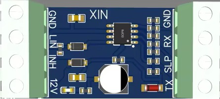
Pin Configuration and Descriptions
The LINTTL3 module has a simple pinout for easy integration into your circuit. The pin configuration is as follows:
| Pin | Name | Description |
|---|---|---|
| 1 | VCC | Power input (5V DC) |
| 2 | GND | Ground connection |
| 3 | TXD | UART Transmit pin (connect to RX of microcontroller) |
| 4 | RXD | UART Receive pin (connect to TX of microcontroller) |
| 5 | LIN | LIN bus signal pin (connect to LIN bus line) |
| 6 | EN | Enable pin (active HIGH, enables LIN communication when set to HIGH) |
Usage Instructions
How to Use the Component in a Circuit
- Power the Module: Connect the
VCCpin to a 5V DC power source and theGNDpin to the ground. - Connect UART Lines:
- Connect the
TXDpin of the module to theRXpin of your microcontroller. - Connect the
RXDpin of the module to theTXpin of your microcontroller.
- Connect the
- Connect the LIN Bus: Attach the
LINpin to the LIN bus line in your system. - Enable the Module: Set the
ENpin to HIGH to activate LIN communication. - Configure Baud Rates: Ensure that the UART baud rate of your microcontroller matches the module's UART baud rate. Similarly, configure the LIN bus baud rate as required by your application.
Important Considerations and Best Practices
- Voltage Levels: Ensure that the microcontroller's UART pins operate at 5V logic levels. If your microcontroller uses 3.3V logic, use a level shifter to avoid damage to the module.
- Termination Resistor: If the LIN bus does not already have a termination resistor, add a 1kΩ pull-up resistor between the
LINpin andVCC. - Noise Reduction: Keep the LIN bus wiring as short as possible to minimize noise and signal degradation.
- Enable Pin Control: Use a GPIO pin on your microcontroller to control the
ENpin, allowing you to enable or disable LIN communication programmatically.
Example Code for Arduino UNO
Below is an example Arduino sketch to demonstrate communication with the LINTTL3 module:
// Example: Sending data over LIN bus using LINTTL3 module
// Ensure the module is connected to the Arduino as follows:
// TXD -> Pin 2 (RX), RXD -> Pin 3 (TX), EN -> Pin 4, LIN -> LIN bus line

#include <SoftwareSerial.h>

// Define pins for SoftwareSerial
#define RX_PIN 2  // Arduino RX (connect to TXD of LINTTL3)
#define TX_PIN 3  // Arduino TX (connect to RXD of LINTTL3)
#define EN_PIN 4  // Enable pin (connect to EN of LINTTL3)

// Create a SoftwareSerial object
SoftwareSerial linSerial(RX_PIN, TX_PIN);

void setup() {
  // Initialize serial communication
  Serial.begin(9600);          // For debugging via Serial Monitor
  linSerial.begin(19200);      // LIN bus baud rate (adjust as needed)

  // Configure the EN pin
  pinMode(EN_PIN, OUTPUT);
  digitalWrite(EN_PIN, HIGH);  // Enable LIN communication

  Serial.println("LINTTL3 Module Initialized");
}

void loop() {
  // Example: Send a message over the LIN bus
  String message = "Hello LIN!";
  linSerial.println(message);  // Send the message via LIN bus

  Serial.println("Message sent: " + message);  // Debug output
  delay(1000);  // Wait 1 second before sending the next message
}
Troubleshooting and FAQs
Common Issues and Solutions
No Communication on LIN Bus
- Cause: The
ENpin is not set to HIGH. - Solution: Ensure the
ENpin is connected to a GPIO pin and set to HIGH in your code.
- Cause: The
Data Corruption or Noise on LIN Bus
- Cause: Long or unshielded LIN bus wiring.
- Solution: Use shorter wires and, if possible, shielded cables to reduce noise.
Module Not Responding
- Cause: Incorrect UART baud rate configuration.
- Solution: Verify that the UART baud rate of your microcontroller matches the module's settings.
Overheating
- Cause: Excessive current draw or incorrect wiring.
- Solution: Double-check all connections and ensure the module is powered with 5V DC.
FAQs
Q: Can I use this module with a 3.3V microcontroller?
A: Yes, but you must use a level shifter to convert the 3.3V UART signals to 5V logic levels.
Q: What is the maximum length of the LIN bus?
A: The LIN bus can typically support lengths up to 40 meters, but shorter lengths are recommended for better signal integrity.
Q: Does the module support LIN 2.1?
A: The module is compatible with LIN 2.0 and LIN 1.3. Compatibility with LIN 2.1 depends on the specific implementation and features used.
Q: Can I use this module for multi-node LIN networks?
A: Yes, the module can be used in multi-node LIN networks, but ensure proper termination and master/slave configuration.