How to Use Convertidor Voltaje DC-DC Step-Down 2A MP2315: Examples, Pinouts, and Specs
Introduction
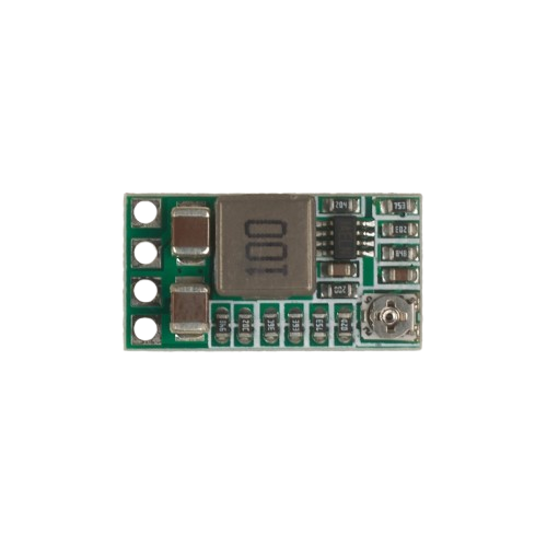
The MP2315 is a high-efficiency DC-DC step-down converter manufactured by MPS (Monolithic Power Systems). It is designed to step down higher DC input voltages to lower DC output voltages while delivering up to 2A of continuous output current. This compact and reliable component is ideal for applications requiring efficient power conversion, such as powering microcontrollers, sensors, and other low-voltage devices from higher voltage sources like batteries or power adapters.
Explore Projects Built with Convertidor Voltaje DC-DC Step-Down 2A MP2315


Explore Projects Built with Convertidor Voltaje DC-DC Step-Down 2A MP2315
Common Applications and Use Cases
- Powering microcontrollers (e.g., Arduino, ESP32) and sensors
- Battery-powered devices and portable electronics
- Industrial and automotive systems
- LED drivers and lighting systems
- General-purpose voltage regulation in embedded systems
Technical Specifications
The following table outlines the key technical specifications of the MP2315:
| Parameter | Value |
|---|---|
| Input Voltage Range | 4.5V to 24V |
| Output Voltage Range | 0.6V to 12V (adjustable via feedback) |
| Maximum Output Current | 2A |
| Efficiency | Up to 95% |
| Switching Frequency | 1.4MHz |
| Feedback Voltage | 0.6V |
| Operating Temperature | -40°C to +85°C |
| Package Type | SOT23-6 |
Pin Configuration and Descriptions
The MP2315 comes in a compact SOT23-6 package with the following pinout:
| Pin Number | Pin Name | Description |
|---|---|---|
| 1 | VIN | Input voltage pin. Connect to the DC input source (4.5V to 24V). |
| 2 | SW | Switching node. Connect to the inductor and diode. |
| 3 | GND | Ground pin. Connect to the system ground. |
| 4 | FB | Feedback pin. Connect to a resistor divider to set the output voltage. |
| 5 | EN | Enable pin. Drive high to enable the converter, or low to disable it. |
| 6 | BST | Bootstrap pin. Connect a capacitor (e.g., 0.1µF) between BST and SW. |
Usage Instructions
How to Use the MP2315 in a Circuit
- Input Voltage: Connect the input voltage (4.5V to 24V) to the VIN pin. Use a decoupling capacitor (e.g., 10µF) close to the VIN pin to reduce input noise.
- Output Voltage: Use a resistor divider network connected to the FB pin to set the desired output voltage. The output voltage is calculated using the formula: [ V_{OUT} = V_{FB} \times \left(1 + \frac{R1}{R2}\right) ] where ( V_{FB} = 0.6V ), ( R1 ) is the resistor connected between VOUT and FB, and ( R2 ) is the resistor connected between FB and GND.
- Inductor Selection: Choose an inductor with a suitable value (e.g., 4.7µH to 22µH) and a current rating higher than the maximum output current (2A).
- Bootstrap Capacitor: Connect a 0.1µF ceramic capacitor between the BST and SW pins.
- Enable Pin: Drive the EN pin high (e.g., connect to VIN) to enable the converter. Pull it low to disable the converter.
- Output Capacitor: Use a low-ESR ceramic capacitor (e.g., 22µF) at the output to stabilize the voltage and reduce ripple.
Example Circuit
Below is a typical application circuit for the MP2315:
VIN (4.5V-24V) ----+----[10µF]----+---- VIN (Pin 1)
                   |              |
                  [R1]           [L] (Inductor)
                   |              |
                  FB (Pin 4)     SW (Pin 2)
                   |              |
                  [R2]           [D] (Diode)
                   |              |
                  GND (Pin 3)    VOUT (to load)
Arduino UNO Example Code
The MP2315 can be used to power an Arduino UNO by stepping down a higher voltage (e.g., 12V) to 5V. Below is an example code to blink an LED connected to the Arduino UNO, assuming the MP2315 is used to supply 5V to the Arduino:
// Example code to blink an LED using Arduino UNO
// Ensure the MP2315 is configured to output 5V to power the Arduino

const int ledPin = 13; // Built-in LED pin on Arduino UNO

void setup() {
  pinMode(ledPin, OUTPUT); // Set the LED pin as an output
}

void loop() {
  digitalWrite(ledPin, HIGH); // Turn the LED on
  delay(1000);                // Wait for 1 second
  digitalWrite(ledPin, LOW);  // Turn the LED off
  delay(1000);                // Wait for 1 second
}
Important Considerations and Best Practices
- Thermal Management: Ensure proper heat dissipation, especially when operating at high currents. Use a PCB with good thermal conductivity.
- Input Voltage Range: Do not exceed the maximum input voltage of 24V to avoid damaging the component.
- Output Voltage Accuracy: Use precision resistors for the feedback network to achieve accurate output voltage.
- Inductor Selection: Choose an inductor with low DC resistance (DCR) to minimize power losses.
Troubleshooting and FAQs
Common Issues and Solutions
No Output Voltage:
- Check if the EN pin is properly driven high to enable the converter.
- Verify the input voltage is within the specified range (4.5V to 24V).
- Inspect the feedback resistor network for incorrect values or poor connections.
Excessive Output Ripple:
- Ensure the output capacitor has a low ESR and sufficient capacitance (e.g., 22µF or higher).
- Verify the inductor value is appropriate for the application.
Overheating:
- Check for excessive load current exceeding the 2A limit.
- Improve thermal management by adding copper planes or heat sinks.
Incorrect Output Voltage:
- Recalculate the resistor divider values for the desired output voltage.
- Verify the feedback pin (FB) is properly connected.
FAQs
Q: Can the MP2315 be used with a 3.3V output?
A: Yes, the MP2315 can be configured to output 3.3V by selecting the appropriate resistor divider values.
Q: What is the maximum input voltage for the MP2315?
A: The maximum input voltage is 24V. Exceeding this value may damage the component.
Q: Can the MP2315 operate without a load?
A: Yes, the MP2315 can operate without a load, but ensure the feedback network is properly configured to maintain stability.
Q: Is the MP2315 suitable for battery-powered applications?
A: Yes, the MP2315 is highly efficient and ideal for battery-powered devices, as it minimizes power losses.