
How to Use MICS5524 Module: Examples, Pinouts, and Specs
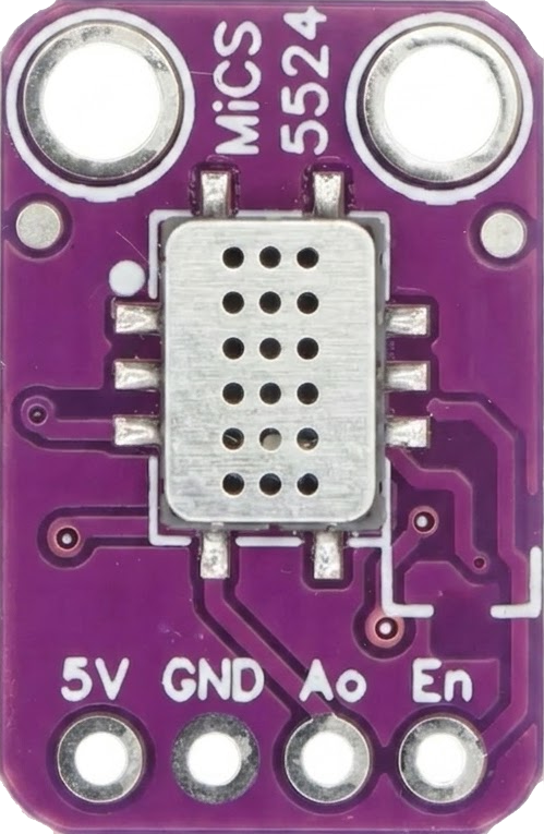
 Design with MICS5524 Module in Cirkit Designer
Introduction
The MICS5524 Module, manufactured by SGX Sensortech (Amphenol), is a compact and versatile gas sensor designed to detect a variety of gases, including carbon monoxide (CO), methane (CH₄), and liquefied petroleum gas (LPG). This sensor operates on low voltage and provides an analog output, making it ideal for applications such as air quality monitoring, industrial safety systems, and smart home devices.
The MICS5524 is particularly valued for its sensitivity, low power consumption, and ease of integration into electronic systems. Its small form factor and reliable performance make it a popular choice for both hobbyists and professionals.
Explore Projects Built with MICS5524 Module
 Open Project in Cirkit Designer
 Open Project in Cirkit Designer
 Open Project in Cirkit Designer
 Open Project in Cirkit Designer
Explore Projects Built with MICS5524 Module
Open Project in Cirkit DesignerOpen Project in Cirkit DesignerOpen Project in Cirkit DesignerOpen Project in Cirkit DesignerTechnical Specifications
Below are the key technical details of the MICS5524 Module:
General Specifications
| Parameter | Value |
|---|---|
| Manufacturer | SGX Sensortech (Amphenol) |
| Part Number | MICS5524 |
| Gas Detection | CO, CH₄, LPG |
| Operating Voltage | 2.5 V to 5 V |
| Heater Voltage (VH) | 1.4 V ± 0.1 V |
| Heater Power Consumption | ~15 mW |
| Analog Output Range | 0 V to 5 V |
| Operating Temperature | -20°C to +50°C |
| Storage Temperature | -40°C to +70°C |
| Dimensions | 5 mm x 5 mm x 3 mm |
Pin Configuration and Descriptions
The MICS5524 Module typically has the following pinout:
| Pin Number | Pin Name | Description |
|---|---|---|
| 1 | VCC | Power supply input (2.5 V to 5 V) |
| 2 | GND | Ground connection |
| 3 | OUT | Analog output signal proportional to gas levels |
| 4 | NC | Not connected (leave unconnected) |
Usage Instructions
How to Use the MICS5524 Module in a Circuit
- Power Supply: Connect the VCC pin to a regulated power source (2.5 V to 5 V) and the GND pin to the ground of your circuit.
- Signal Output: The OUT pin provides an analog voltage proportional to the concentration of detected gases. This output can be read using an ADC (Analog-to-Digital Converter) on a microcontroller or an external ADC module.
- Preheating: Allow the sensor to preheat for at least 2 minutes after powering it on to ensure accurate readings.
- Signal Processing: Use the analog output to calculate gas concentration. The relationship between the output voltage and gas concentration can be determined using the sensor's calibration data (refer to the manufacturer's datasheet for detailed calibration curves).
Important Considerations and Best Practices
- Ventilation: Ensure the sensor is exposed to the air or gas sample for accurate detection.
- Avoid Contaminants: Protect the sensor from dust, oil, and other contaminants that may affect its performance.
- Temperature and Humidity: Operate the sensor within the specified temperature and humidity range to avoid damage or inaccurate readings.
- Calibration: Periodically calibrate the sensor for consistent performance, especially in long-term applications.
- Arduino Compatibility: The MICS5524 Module can be easily interfaced with an Arduino UNO or similar microcontrollers.
Example Arduino Code
Below is an example of how to interface the MICS5524 Module with an Arduino UNO to read the analog output:
// Define the analog pin connected to the MICS5524 OUT pin
const int sensorPin = A0;

void setup() {
  Serial.begin(9600); // Initialize serial communication at 9600 baud
  pinMode(sensorPin, INPUT); // Set the sensor pin as input
}

void loop() {
  int sensorValue = analogRead(sensorPin);
  // Read the analog value from the sensor

  float voltage = sensorValue * (5.0 / 1023.0);
  // Convert the analog value to voltage (assuming 5V reference)

  Serial.print("Sensor Voltage: ");
  Serial.print(voltage);
  Serial.println(" V");

  delay(1000); // Wait for 1 second before the next reading
}
Notes on the Code
- Ensure the Arduino's 5V pin is connected to the MICS5524's VCC pin and the GND pin is connected to the Arduino's ground.
- The analog output voltage can be used to estimate gas concentration based on the sensor's calibration data.
Troubleshooting and FAQs
Common Issues and Solutions
No Output Signal:
- Cause: Incorrect wiring or insufficient power supply.
- Solution: Double-check the connections and ensure the power supply voltage is within the specified range (2.5 V to 5 V).
Inaccurate Readings:
- Cause: Insufficient preheating time or environmental interference.
- Solution: Allow the sensor to preheat for at least 2 minutes and ensure the sensor is placed in a stable environment.
Output Voltage Stuck at Maximum or Minimum:
- Cause: Sensor damage or contamination.
- Solution: Inspect the sensor for physical damage or contamination. Replace the sensor if necessary.
Fluctuating Readings:
- Cause: Electrical noise or unstable power supply.
- Solution: Use a decoupling capacitor (e.g., 0.1 µF) across the power supply pins to reduce noise.
FAQs
Q1: Can the MICS5524 detect gases other than CO, CH₄, and LPG?
A1: The MICS5524 is optimized for CO, CH₄, and LPG detection, but it may respond to other gases. Refer to the manufacturer's datasheet for cross-sensitivity information.
Q2: How do I calibrate the sensor?
A2: Calibration involves exposing the sensor to known concentrations of target gases and recording the output voltage. Use this data to create a calibration curve for accurate measurements.
Q3: Can I use the MICS5524 outdoors?
A3: The sensor can be used outdoors, but it should be protected from extreme weather conditions, dust, and contaminants.
Q4: What is the lifespan of the MICS5524?
A4: The sensor has a typical lifespan of several years under normal operating conditions. Regular calibration and proper handling can extend its life.
By following this documentation, users can effectively integrate the MICS5524 Module into their projects and ensure reliable gas detection performance.