Cirkit Designer Logo
Cirkit Designer
Your all-in-one circuit design IDE
Home / 
Component Documentation

How to Use CVMC10: Examples, Pinouts, and Specs

Image of CVMC10
Cirkit Designer LogoDesign with CVMC10 in Cirkit Designer

Introduction

The CVMC10 is a compact voltage-controlled oscillator (VCO) manufactured by Circurator with the part ID C10. It is designed for generating high-frequency signals with low phase noise, making it an essential component in communication systems, signal processing, and frequency synthesis applications. The CVMC10 offers excellent frequency stability and a wide tuning range, making it suitable for both professional and hobbyist projects.

Explore Projects Built with CVMC10

Use Cirkit Designer to design, explore, and prototype these projects online. Some projects support real-time simulation. Click "Open Project" to start designing instantly!
Battery-Powered Remote-Controlled Dual Motor System with Cytron URC10
Image of URC10 SUMO RC: A project utilizing CVMC10 in a practical application
This circuit is a remote-controlled dual DC motor driver system powered by a 3S LiPo battery. It uses a Cytron URC10 motor driver to control two GM25 DC motors based on signals received from an R6FG receiver, with a rocker switch for power control and a 7-segment panel voltmeter for monitoring the battery voltage.
Cirkit Designer LogoOpen Project in Cirkit Designer
Battery-Powered Line Following Robot with IR Sensors and Cytron URC10 Motor Controller
Image of URC10 SUMO AUTO: A project utilizing CVMC10 in a practical application
This circuit is a robotic control system that uses multiple IR sensors for line detection and obstacle avoidance, powered by a 3S LiPo battery. The Cytron URC10 motor driver, controlled by a microcontroller, drives two GM25 DC motors based on input from the sensors and a rocker switch, with a 7-segment panel voltmeter displaying the battery voltage.
Cirkit Designer LogoOpen Project in Cirkit Designer
Beelink Mini S12 N95 and Arduino UNO Based Fingerprint Authentication System with ESP32 CAM
Image of design 3: A project utilizing CVMC10 in a practical application
This circuit features a Beelink MINI S12 N95 computer connected to a 7-inch display via HDMI for video output and two USB connections for power and touch screen functionality. An Arduino UNO is interfaced with a fingerprint scanner for biometric input. The Beelink MINI S12 N95 is powered by a PC power supply, which in turn is connected to a 240V power source. Additionally, an ESP32 CAM module is powered and programmed via a USB plug and an FTDI programmer, respectively, for wireless camera capabilities.
Cirkit Designer LogoOpen Project in Cirkit Designer
Arduino-Controlled Medication Reminder System with GSM Alert and Weight Sensing
Image of tablet machine: A project utilizing CVMC10 in a practical application
This circuit is designed as a medication reminder system with three compartments, each driven by a DC motor for opening and closing. One compartment is equipped with a weight sensor (HX711 with a load cell) to detect medication removal, and a GSM module (SIM800L) is used to send alerts if medication is not taken. The system is controlled by an Arduino UNO, which schedules the opening of compartments and monitors the weight sensor, while also interfacing with a real-time clock (RTC) module for timekeeping and a DFPlayer Mini for audio feedback.
Cirkit Designer LogoOpen Project in Cirkit Designer

Explore Projects Built with CVMC10

Use Cirkit Designer to design, explore, and prototype these projects online. Some projects support real-time simulation. Click "Open Project" to start designing instantly!
Image of URC10 SUMO RC: A project utilizing CVMC10 in a practical application
Battery-Powered Remote-Controlled Dual Motor System with Cytron URC10
This circuit is a remote-controlled dual DC motor driver system powered by a 3S LiPo battery. It uses a Cytron URC10 motor driver to control two GM25 DC motors based on signals received from an R6FG receiver, with a rocker switch for power control and a 7-segment panel voltmeter for monitoring the battery voltage.
Cirkit Designer LogoOpen Project in Cirkit Designer
Image of URC10 SUMO AUTO: A project utilizing CVMC10 in a practical application
Battery-Powered Line Following Robot with IR Sensors and Cytron URC10 Motor Controller
This circuit is a robotic control system that uses multiple IR sensors for line detection and obstacle avoidance, powered by a 3S LiPo battery. The Cytron URC10 motor driver, controlled by a microcontroller, drives two GM25 DC motors based on input from the sensors and a rocker switch, with a 7-segment panel voltmeter displaying the battery voltage.
Cirkit Designer LogoOpen Project in Cirkit Designer
Image of design 3: A project utilizing CVMC10 in a practical application
Beelink Mini S12 N95 and Arduino UNO Based Fingerprint Authentication System with ESP32 CAM
This circuit features a Beelink MINI S12 N95 computer connected to a 7-inch display via HDMI for video output and two USB connections for power and touch screen functionality. An Arduino UNO is interfaced with a fingerprint scanner for biometric input. The Beelink MINI S12 N95 is powered by a PC power supply, which in turn is connected to a 240V power source. Additionally, an ESP32 CAM module is powered and programmed via a USB plug and an FTDI programmer, respectively, for wireless camera capabilities.
Cirkit Designer LogoOpen Project in Cirkit Designer
Image of tablet machine: A project utilizing CVMC10 in a practical application
Arduino-Controlled Medication Reminder System with GSM Alert and Weight Sensing
This circuit is designed as a medication reminder system with three compartments, each driven by a DC motor for opening and closing. One compartment is equipped with a weight sensor (HX711 with a load cell) to detect medication removal, and a GSM module (SIM800L) is used to send alerts if medication is not taken. The system is controlled by an Arduino UNO, which schedules the opening of compartments and monitors the weight sensor, while also interfacing with a real-time clock (RTC) module for timekeeping and a DFPlayer Mini for audio feedback.
Cirkit Designer LogoOpen Project in Cirkit Designer

Common Applications

  • Wireless communication systems (e.g., RF transmitters and receivers)
  • Signal generators and frequency synthesizers
  • Phase-locked loops (PLLs)
  • Radar and satellite communication systems
  • Test and measurement equipment

Technical Specifications

Key Specifications

Parameter Value
Supply Voltage (Vcc) 3.3V to 5.0V
Tuning Voltage Range 0.5V to 4.5V
Frequency Range 100 MHz to 1 GHz
Phase Noise -120 dBc/Hz at 100 kHz offset
Output Power +5 dBm (typical)
Output Impedance 50 Ω
Operating Temperature -40°C to +85°C
Package Type 8-pin SOIC

Pin Configuration and Descriptions

The CVMC10 is housed in an 8-pin SOIC package. The pinout and descriptions are as follows:

Pin Number Pin Name Description
1 Vcc Positive supply voltage (3.3V to 5.0V).
2 GND Ground connection.
3 TUNE Tuning voltage input (0.5V to 4.5V).
4 NC No connection (leave unconnected).
5 OUT RF output signal (50 Ω impedance).
6 NC No connection (leave unconnected).
7 ENABLE Enable/disable control (logic high to enable).
8 GND Ground connection.

Usage Instructions

How to Use the CVMC10 in a Circuit

  1. Power Supply: Connect the Vcc pin to a stable DC power supply (3.3V to 5.0V) and the GND pins to the ground of the circuit.
  2. Tuning Voltage: Apply a tuning voltage (0.5V to 4.5V) to the TUNE pin to control the output frequency. The frequency increases with the tuning voltage.
  3. Output Signal: The RF output signal is available at the OUT pin. Use a 50 Ω load for optimal performance.
  4. Enable/Disable: Use the ENABLE pin to control the oscillator. Apply a logic high signal to enable the VCO and a logic low signal to disable it.
  5. Bypass Capacitors: Place decoupling capacitors (e.g., 0.1 µF and 10 µF) close to the Vcc pin to reduce noise and ensure stable operation.

Important Considerations and Best Practices

  • Ensure the tuning voltage does not exceed the specified range (0.5V to 4.5V) to avoid damaging the component.
  • Use a low-noise power supply to minimize phase noise in the output signal.
  • Keep the RF output trace as short as possible and use proper impedance matching techniques to maintain signal integrity.
  • Avoid placing the CVMC10 near high-power or noisy components to prevent interference.

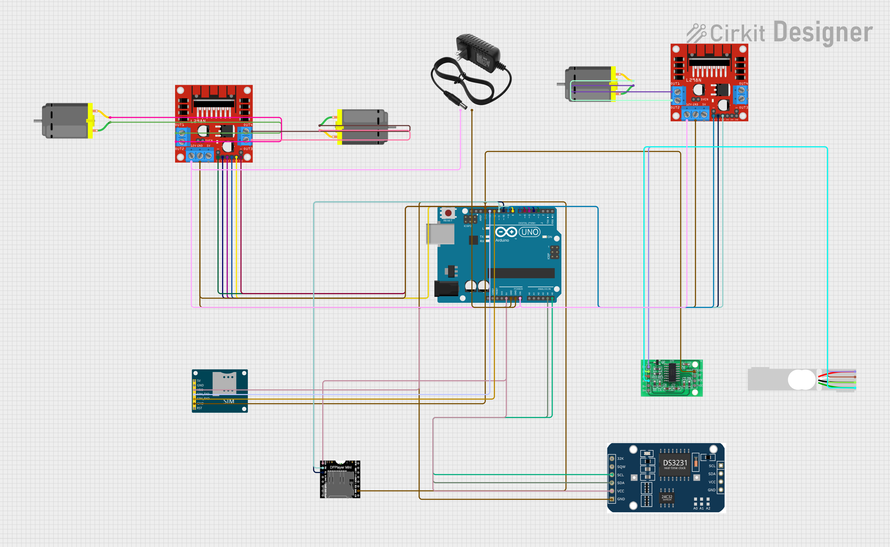
Example: Using CVMC10 with Arduino UNO

The CVMC10 can be controlled using an Arduino UNO to generate a variable frequency output. Below is an example code to control the tuning voltage using a PWM signal.

// Example: Controlling CVMC10 tuning voltage with Arduino UNO
// This code generates a PWM signal to control the tuning voltage of the CVMC10.
// Ensure a low-pass filter is used to convert the PWM signal to a stable DC voltage.

const int pwmPin = 9; // PWM output pin connected to the TUNE pin of CVMC10

void setup() {
  pinMode(pwmPin, OUTPUT); // Set the PWM pin as an output
}

void loop() {
  for (int dutyCycle = 0; dutyCycle <= 255; dutyCycle++) {
    // Gradually increase the PWM duty cycle from 0 to 255
    analogWrite(pwmPin, dutyCycle);
    delay(20); // Wait for 20ms before increasing the duty cycle
  }

  for (int dutyCycle = 255; dutyCycle >= 0; dutyCycle--) {
    // Gradually decrease the PWM duty cycle from 255 to 0
    analogWrite(pwmPin, dutyCycle);
    delay(20); // Wait for 20ms before decreasing the duty cycle
  }
}

Note: Use a low-pass RC filter (e.g., 10 kΩ resistor and 0.1 µF capacitor) to smooth the PWM signal into a stable DC voltage before connecting it to the TUNE pin.

Troubleshooting and FAQs

Common Issues and Solutions

  1. No Output Signal:

    • Ensure the ENABLE pin is set to logic high.
    • Verify the power supply voltage is within the specified range (3.3V to 5.0V).
    • Check the tuning voltage and ensure it is within the 0.5V to 4.5V range.
  2. High Phase Noise:

    • Use a low-noise power supply and proper decoupling capacitors.
    • Minimize interference from nearby components by proper PCB layout design.
  3. Output Frequency is Incorrect:

    • Verify the tuning voltage applied to the TUNE pin.
    • Check for any impedance mismatches in the output signal path.
  4. Component Overheating:

    • Ensure the supply voltage does not exceed 5.0V.
    • Check for short circuits or excessive current draw in the circuit.

FAQs

Q1: Can the CVMC10 operate at frequencies below 100 MHz?
A1: No, the CVMC10 is designed to operate within the specified frequency range of 100 MHz to 1 GHz.

Q2: What happens if the tuning voltage exceeds 4.5V?
A2: Applying a tuning voltage beyond the specified range may damage the component or result in unpredictable behavior.

Q3: Can I use the CVMC10 with a 3.3V power supply?
A3: Yes, the CVMC10 supports a supply voltage range of 3.3V to 5.0V. Ensure the tuning voltage is scaled accordingly.

Q4: Is the CVMC10 suitable for battery-powered applications?
A4: Yes, its low power consumption and wide operating voltage range make it suitable for battery-powered designs.