
How to Use MH-ET Live: Examples, Pinouts, and Specs
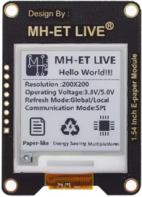
 Design with MH-ET Live in Cirkit Designer
Introduction
The MH-ET Live ePaper module is a versatile and user-friendly platform designed for real-time data visualization and monitoring. It is widely used in educational and experimental settings to analyze electronic circuits and systems. This component leverages ePaper display technology, which is known for its low power consumption and excellent readability in various lighting conditions. Its compact design and ease of integration make it a popular choice for hobbyists, educators, and engineers.
Explore Projects Built with MH-ET Live
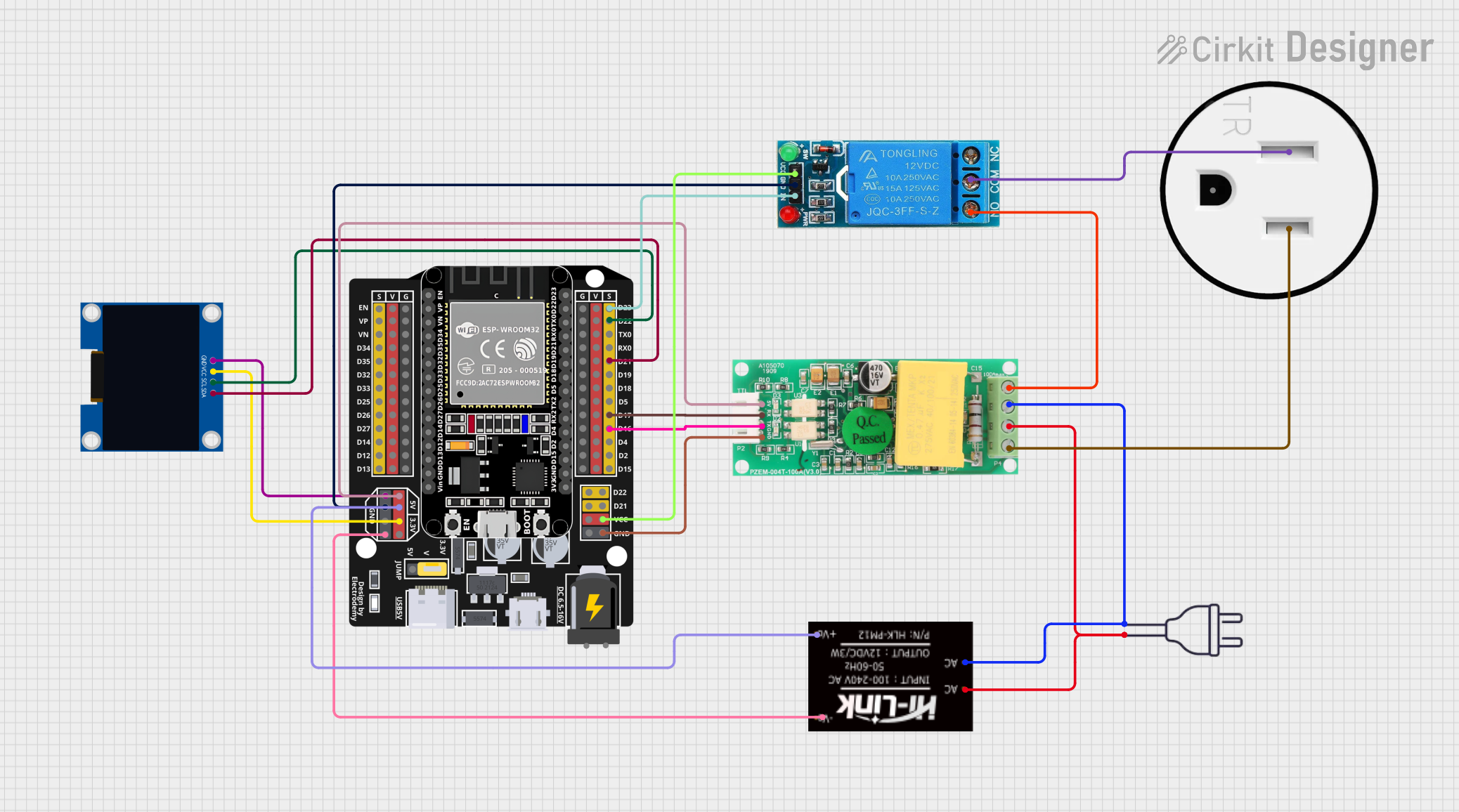 Open Project in Cirkit Designer
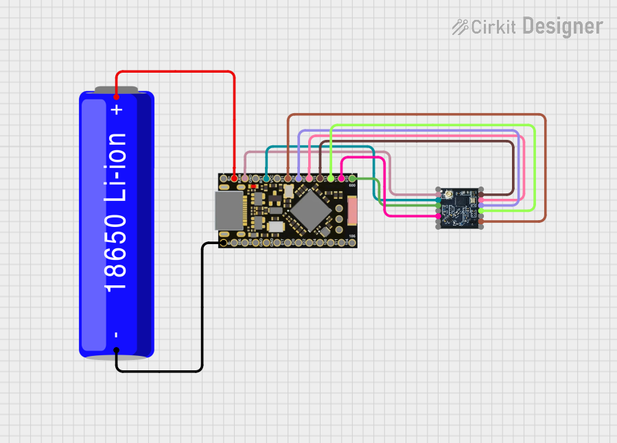 Open Project in Cirkit Designer
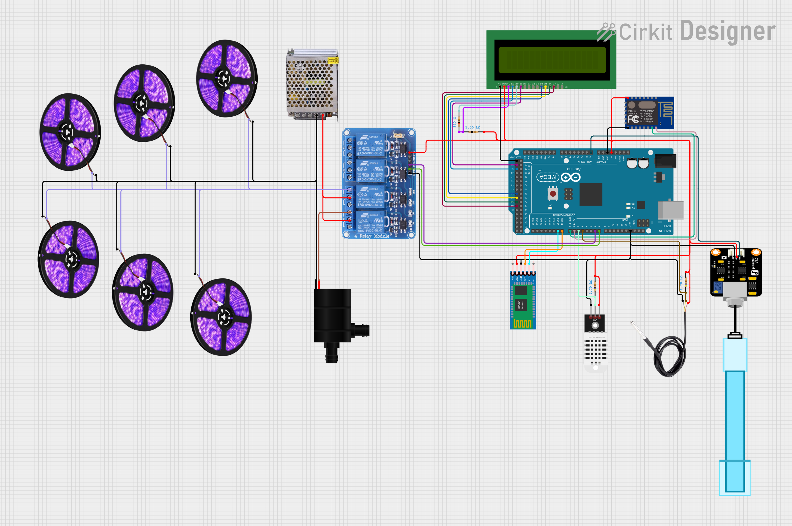 Open Project in Cirkit Designer
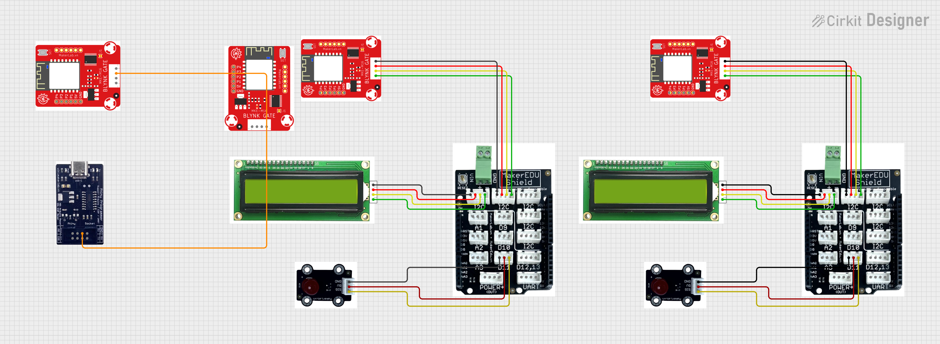 Open Project in Cirkit Designer
Explore Projects Built with MH-ET Live
Open Project in Cirkit DesignerOpen Project in Cirkit DesignerOpen Project in Cirkit DesignerOpen Project in Cirkit DesignerCommon Applications and Use Cases
- Real-time data monitoring in IoT projects
- Displaying sensor data in educational experiments
- Low-power electronic signage
- Portable electronic devices requiring high-contrast displays
- Circuit analysis and debugging tools
Technical Specifications
The MH-ET Live ePaper module is designed to be compatible with a wide range of microcontrollers, including Arduino boards. Below are the key technical details:
General Specifications
| Parameter | Value |
|---|---|
| Display Type | ePaper (Electronic Paper) |
| Resolution | 200 x 200 pixels |
| Display Size | 1.54 inches |
| Interface | SPI (Serial Peripheral Interface) |
| Operating Voltage | 3.3V |
| Power Consumption | Ultra-low (only during refresh) |
| Refresh Time | ~2 seconds |
| Viewing Angle | 180° |
| Operating Temperature | -20°C to 70°C |
Pin Configuration and Descriptions
| Pin Name | Pin Number | Description |
|---|---|---|
| VCC | 1 | Power supply input (3.3V) |
| GND | 2 | Ground connection |
| DIN | 3 | SPI data input |
| CLK | 4 | SPI clock input |
| CS | 5 | Chip select (active low) |
| DC | 6 | Data/Command control pin |
| RST | 7 | Reset pin (active low) |
| BUSY | 8 | Busy status output (high when refreshing) |
Usage Instructions
How to Use the Component in a Circuit
- Power Supply: Connect the VCC pin to a 3.3V power source and the GND pin to ground.
- SPI Communication: Connect the DIN, CLK, and CS pins to the corresponding SPI pins on your microcontroller.
- Control Pins:
- Connect the DC pin to a GPIO pin on your microcontroller to toggle between data and command modes.
- Connect the RST pin to a GPIO pin for resetting the module.
- Connect the BUSY pin to a GPIO pin to monitor the module's status.
- Software Setup: Use an appropriate library (e.g., GxEPD for Arduino) to control the ePaper display.
Important Considerations and Best Practices
- Power Supply: Ensure a stable 3.3V power source to avoid damage to the module.
- Refresh Rate: The ePaper display has a slow refresh rate (~2 seconds). Avoid frequent updates to preserve the display's lifespan.
- Handling: ePaper displays are fragile. Handle the module carefully to avoid physical damage.
- Library Compatibility: Use libraries specifically designed for ePaper displays to simplify development.
Example Code for Arduino UNO
Below is an example of how to use the MH-ET Live ePaper module with an Arduino UNO:
#include <GxEPD.h>          // Include the GxEPD library for ePaper displays
#include <GxGDEH0154D67.h>  // Include the specific driver for the 1.54-inch display
#include <Adafruit_GFX.h>   // Include Adafruit GFX library for graphics support

// Define the pins connected to the ePaper module
#define CS_PIN 10   // Chip select pin
#define DC_PIN 9    // Data/Command pin
#define RST_PIN 8   // Reset pin
#define BUSY_PIN 7  // Busy pin

// Initialize the ePaper display
GxIO_Class io(SPI, CS_PIN, DC_PIN, RST_PIN);
GxEPD_Class display(io, RST_PIN, BUSY_PIN);

void setup() {
  display.init();  // Initialize the display
  display.setRotation(1);  // Set display rotation (0-3)

  // Clear the display and set a message
  display.fillScreen(GxEPD_WHITE);  // Clear to white
  display.setTextColor(GxEPD_BLACK);  // Set text color to black
  display.setCursor(10, 50);  // Set cursor position
  display.setTextSize(2);  // Set text size
  display.print("Hello, ePaper!");  // Print message
  display.display();  // Refresh the display
}

void loop() {
  // No actions in the loop for this example
}
Troubleshooting and FAQs
Common Issues and Solutions
Display Not Turning On:
- Verify the power supply is 3.3V and connections are secure.
- Check the wiring of the SPI pins and ensure they match the microcontroller's SPI configuration.
Display Refresh is Slow:
- This is a characteristic of ePaper technology. Avoid frequent updates to improve performance.
Module Not Responding:
- Ensure the RST pin is properly connected and the module is reset during initialization.
- Check the BUSY pin to confirm the module is not in a busy state.
Partial or Corrupted Display:
- Verify the SPI communication speed is within the module's supported range.
- Ensure the library being used is compatible with the MH-ET Live module.
FAQs
Q: Can I use the MH-ET Live module with a 5V microcontroller?
A: No, the module operates at 3.3V. Use a level shifter if your microcontroller operates at 5V.
Q: How do I reduce power consumption?
A: The ePaper module consumes power only during refresh. Minimize refresh frequency to save power.
Q: Can I display images on the module?
A: Yes, you can display monochrome images using libraries like GxEPD. Convert images to a compatible format before uploading.
Q: Is the module sunlight-readable?
A: Yes, ePaper displays are highly readable in direct sunlight due to their reflective technology.