How to Use Micro ROS Control Board (ESP32): Examples, Pinouts, and Specs
Introduction
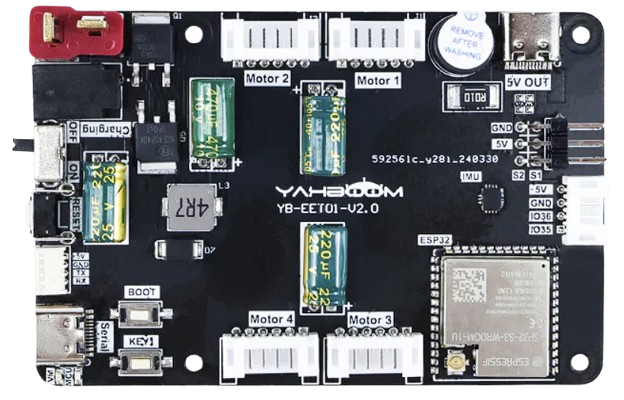
The Micro ROS Control Board (ESP32), manufactured by Yahboom, is a compact and versatile microcontroller board based on the ESP32 chip. It is specifically designed for robotics applications and supports Micro ROS, a lightweight version of the Robot Operating System (ROS) tailored for microcontrollers. This board enables efficient communication and control in robotic systems, making it ideal for projects requiring real-time performance and wireless connectivity.
Explore Projects Built with Micro ROS Control Board (ESP32)
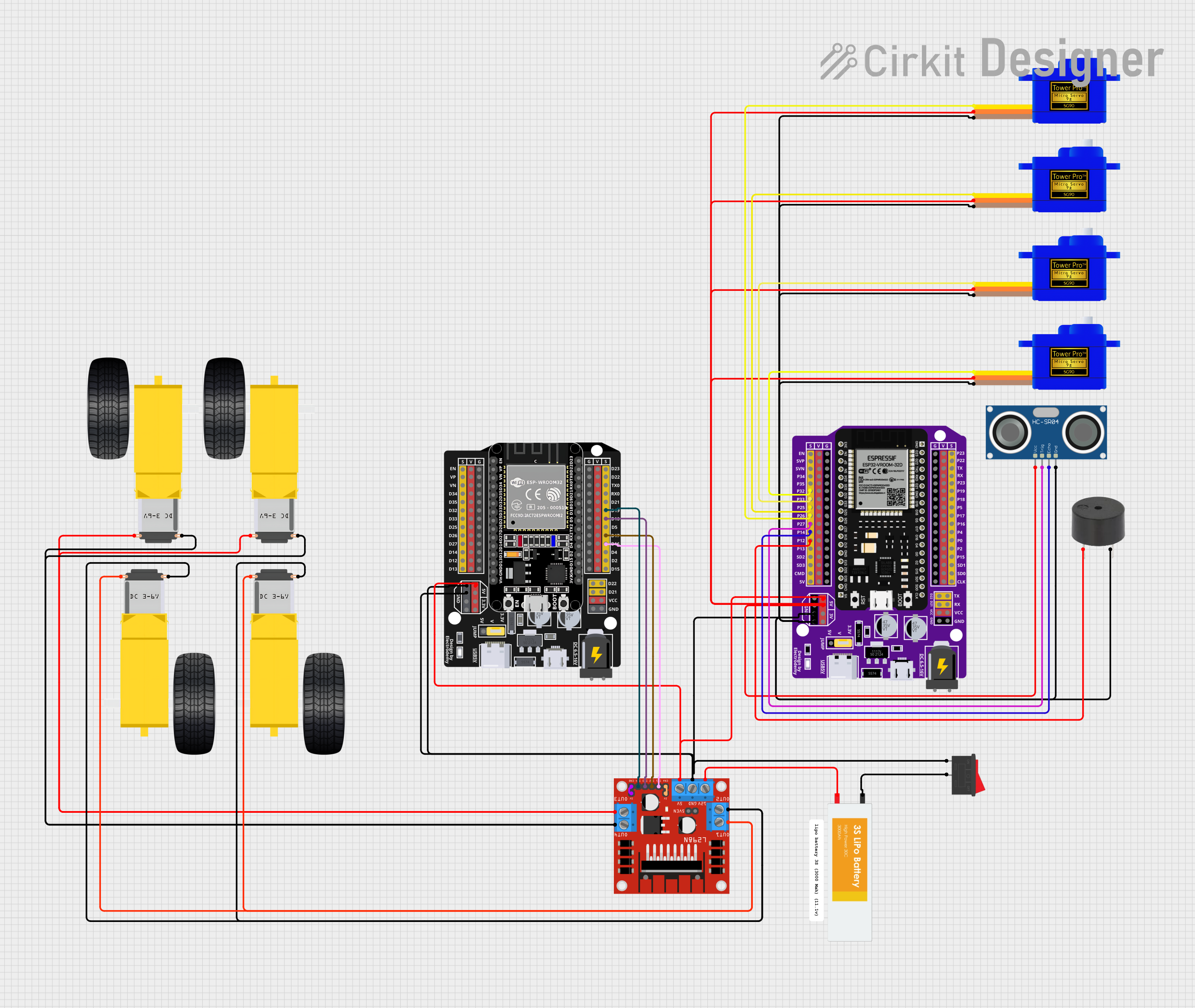
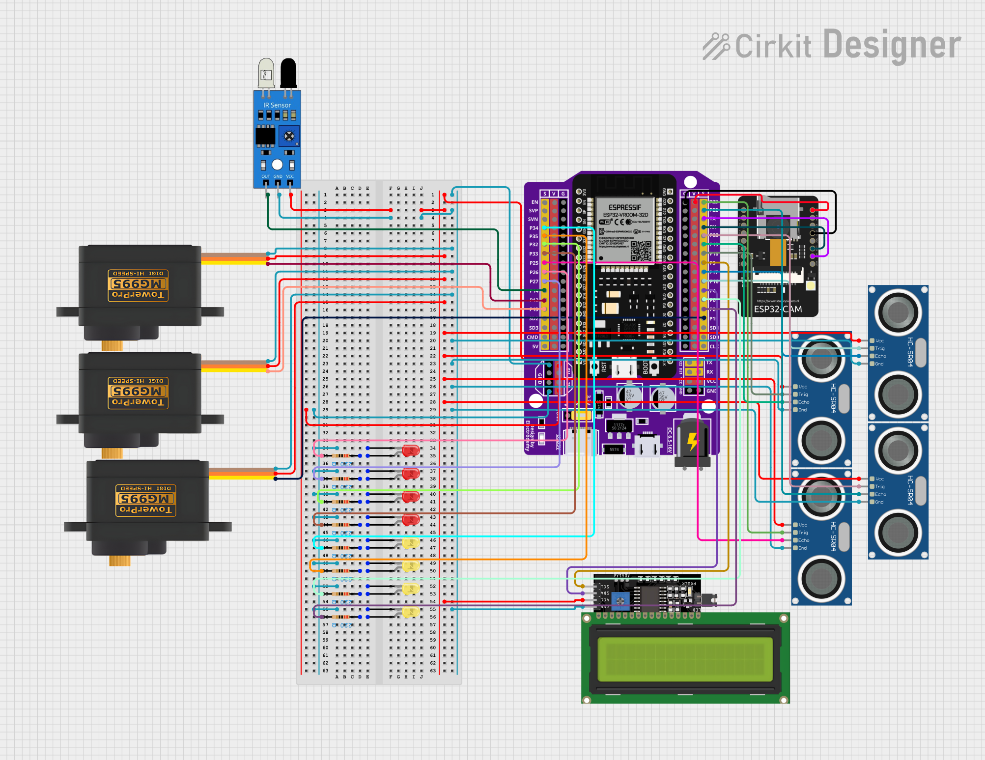

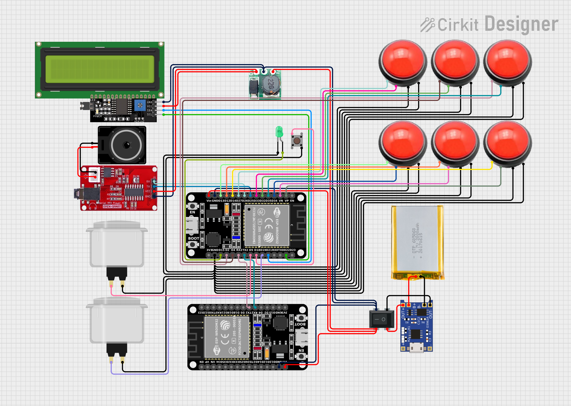
Explore Projects Built with Micro ROS Control Board (ESP32)
Common Applications and Use Cases
- Robotics control systems
- IoT-enabled robotic devices
- Real-time sensor data acquisition and processing
- Wireless communication in robotic networks
- Integration with ROS-based systems for advanced robotics applications
Technical Specifications
Key Technical Details
| Specification | Value |
|---|---|
| Microcontroller | ESP32 Dual-Core Xtensa LX6 |
| Clock Speed | Up to 240 MHz |
| Flash Memory | 4 MB |
| SRAM | 520 KB |
| Wireless Connectivity | Wi-Fi (802.11 b/g/n) and Bluetooth 4.2 |
| Operating Voltage | 3.3V |
| Input Voltage Range | 5V (via USB) |
| GPIO Pins | 30 (including ADC, PWM, I2C, SPI, UART) |
| Communication Protocols | Micro ROS, MQTT, HTTP, WebSocket |
| Dimensions | 58mm x 25mm |
| Power Consumption | ~200 mA (active mode) |
Pin Configuration and Descriptions
| Pin Name | Pin Number | Description |
|---|---|---|
| VIN | 1 | Power input (5V via USB or external source) |
| GND | 2 | Ground |
| GPIO0 | 3 | General-purpose I/O, supports ADC and PWM |
| GPIO1 | 4 | General-purpose I/O, UART TX |
| GPIO2 | 5 | General-purpose I/O, supports ADC and PWM |
| GPIO3 | 6 | General-purpose I/O, UART RX |
| SDA | 7 | I2C Data Line |
| SCL | 8 | I2C Clock Line |
| MOSI | 9 | SPI Master Out Slave In |
| MISO | 10 | SPI Master In Slave Out |
| SCK | 11 | SPI Clock |
| EN | 12 | Enable pin to reset the board |
Usage Instructions
How to Use the Component in a Circuit
Powering the Board:
- Connect the board to a 5V power source via the USB port or the VIN pin.
- Ensure the power supply provides sufficient current (at least 500 mA).
Connecting Peripherals:
- Use the GPIO pins for connecting sensors, actuators, or other peripherals.
- For I2C devices, connect to the SDA and SCL pins.
- For SPI devices, use the MOSI, MISO, and SCK pins.
Programming the Board:
- Install the Arduino IDE or PlatformIO for programming.
- Add the ESP32 board package to your IDE.
- Install the Micro ROS library for ROS integration.
Micro ROS Setup:
- Configure the Micro ROS agent on your ROS-enabled computer.
- Use the Micro ROS library to write firmware for the board, enabling communication with the ROS ecosystem.
Important Considerations and Best Practices
- Voltage Levels: Ensure all connected peripherals operate at 3.3V logic levels to avoid damaging the board.
- Wi-Fi Interference: Place the board away from sources of electromagnetic interference to maintain stable wireless communication.
- Firmware Updates: Regularly update the ESP32 firmware and Micro ROS library for optimal performance and security.
- Heat Management: Avoid prolonged operation at high loads to prevent overheating.
Example Code for Arduino IDE
Below is an example of how to set up the Micro ROS Control Board (ESP32) to publish sensor data to a ROS topic:
#include <micro_ros_arduino.h>
#include <WiFi.h>
#include <std_msgs/String.h>

// Wi-Fi credentials
const char* ssid = "Your_SSID";
const char* password = "Your_PASSWORD";

// ROS node handle
rcl_node_t node;
rcl_publisher_t publisher;
std_msgs__msg__String msg;

// Timer for publishing data
unsigned long last_publish_time = 0;
const unsigned long publish_interval = 1000; // 1 second

void setup() {
  // Initialize serial communication for debugging
  Serial.begin(115200);
  delay(1000);

  // Connect to Wi-Fi
  WiFi.begin(ssid, password);
  while (WiFi.status() != WL_CONNECTED) {
    delay(500);
    Serial.print(".");
  }
  Serial.println("\nWi-Fi connected!");

  // Initialize Micro ROS
  set_microros_wifi_transports(ssid, password, "192.168.1.100", 8888);

  // Create ROS node and publisher
  node = rcl_get_zero_initialized_node();
  rcl_node_init_default(&node, "esp32_node", "", &rcl_get_default_allocator());

  publisher = rcl_get_zero_initialized_publisher();
  rcl_publisher_init_default(
    &publisher, &node, ROSIDL_GET_MSG_TYPE_SUPPORT(std_msgs, msg, String),
    "sensor_data"
  );

  // Prepare message
  msg.data.data = (char*)malloc(50);
  msg.data.size = 0;
  msg.data.capacity = 50;
}

void loop() {
  // Publish data at regular intervals
  if (millis() - last_publish_time >= publish_interval) {
    last_publish_time = millis();

    // Update message content
    snprintf(msg.data.data, msg.data.capacity, "Hello from ESP32 at %lu ms", millis());
    msg.data.size = strlen(msg.data.data);

    // Publish message
    rcl_publish(&publisher, &msg, NULL);
    Serial.println("Message published!");
  }

  // Handle Micro ROS tasks
  rclc_executor_spin_some(NULL, RCL_MS_TO_NS(100));
}
Troubleshooting and FAQs
Common Issues and Solutions
Wi-Fi Connection Fails:
- Double-check the SSID and password.
- Ensure the router is within range and not overloaded with devices.
Micro ROS Agent Not Found:
- Verify the IP address and port of the Micro ROS agent.
- Ensure the agent is running on the ROS-enabled computer.
Board Not Detected by IDE:
- Install the correct USB driver for the ESP32.
- Check the USB cable and port for proper connection.
Overheating:
- Reduce the workload or add a heatsink to the ESP32 chip.
FAQs
Can I use this board without ROS?
Yes, the board can be used as a standard ESP32 microcontroller for non-ROS applications.What is the maximum range of Wi-Fi?
The range depends on the environment but typically extends up to 30 meters indoors.Does the board support OTA updates?
Yes, the ESP32 supports Over-The-Air (OTA) firmware updates.Can I use this board with a LiPo battery?
Yes, but ensure the battery voltage is regulated to 5V before connecting to the VIN pin.