Cirkit Designer Logo
Cirkit Designer
Your all-in-one circuit design IDE
Home / 
Component Documentation

How to Use X10-100: Examples, Pinouts, and Specs

Image of X10-100
Cirkit Designer LogoDesign with X10-100 in Cirkit Designer

Introduction

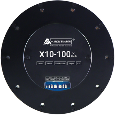
The X10-100, manufactured by Myactuator, is a versatile microcontroller development board designed for prototyping and testing electronic circuits. It features a wide range of input/output (I/O) pins, supports multiple communication protocols, and is compatible with various programming environments. This makes it an excellent choice for both hobbyists and professional engineers working on embedded systems, IoT devices, and automation projects.

Explore Projects Built with X10-100

Use Cirkit Designer to design, explore, and prototype these projects online. Some projects support real-time simulation. Click "Open Project" to start designing instantly!
Satellite-Based Timing and Navigation System with SDR and Atomic Clock Synchronization
Image of GPS 시스템 측정 구성도_Confirm: A project utilizing X10-100 in a practical application
This circuit appears to be a complex system involving power supply management, GPS and timing synchronization, and data communication. It includes a SI-TEX G1 Satellite Compass for GPS data, an XHTF1021 Atomic Rubidium Clock for precise timing, and Ettus USRP B200 units for software-defined radio communication. Power is supplied through various SMPS units and distributed via terminal blocks and DC jacks. Data communication is facilitated by Beelink MINI S12 N95 computers, RS232 splitters, and a 1000BASE-T Media Converter for network connectivity. RF Directional Couplers are used to interface antennas with the USRP units, and the entire system is likely contained within cases for protection and organization.
Cirkit Designer LogoOpen Project in Cirkit Designer
ESP32-Based Smart Energy Monitoring and Control System
Image of SMART SOCKET: A project utilizing X10-100 in a practical application
This circuit is designed to monitor AC voltage and current using ZMPT101B and ZMCT103C sensors, respectively, with an ESP32 microcontroller processing the sensor outputs. The XL4015 step-down module regulates the power supply to provide a stable voltage to the sensors, the ESP32, and an LCD I2C display. The ESP32 controls a 4-channel relay module for switching AC loads, and the system's operation can be interacted with via the LCD display and a push switch.
Cirkit Designer LogoOpen Project in Cirkit Designer
12MHz Crystal Oscillator with 4060 Timer IC and 10k Resistor
Image of 150KHz from 12MHz Crystal oscillator: A project utilizing X10-100 in a practical application
This circuit is a frequency divider using a 4060 binary counter IC and a 12MHz crystal oscillator. It is powered by a 9V battery and provides a divided frequency output at 'Vout'. The 10k Ohm resistor stabilizes the oscillator circuit.
Cirkit Designer LogoOpen Project in Cirkit Designer
Battery-Powered Health Monitoring System with Nucleo WB55RG and OLED Display
Image of Pulsefex: A project utilizing X10-100 in a practical application
This circuit is a multi-sensor data acquisition system that uses a Nucleo WB55RG microcontroller to interface with a digital temperature sensor (TMP102), a pulse oximeter and heart-rate sensor (MAX30102), and a 0.96" OLED display via I2C. Additionally, it includes a Sim800l module for GSM communication, powered by a 3.7V LiPo battery.
Cirkit Designer LogoOpen Project in Cirkit Designer

Explore Projects Built with X10-100

Use Cirkit Designer to design, explore, and prototype these projects online. Some projects support real-time simulation. Click "Open Project" to start designing instantly!
Image of GPS 시스템 측정 구성도_Confirm: A project utilizing X10-100 in a practical application
Satellite-Based Timing and Navigation System with SDR and Atomic Clock Synchronization
This circuit appears to be a complex system involving power supply management, GPS and timing synchronization, and data communication. It includes a SI-TEX G1 Satellite Compass for GPS data, an XHTF1021 Atomic Rubidium Clock for precise timing, and Ettus USRP B200 units for software-defined radio communication. Power is supplied through various SMPS units and distributed via terminal blocks and DC jacks. Data communication is facilitated by Beelink MINI S12 N95 computers, RS232 splitters, and a 1000BASE-T Media Converter for network connectivity. RF Directional Couplers are used to interface antennas with the USRP units, and the entire system is likely contained within cases for protection and organization.
Cirkit Designer LogoOpen Project in Cirkit Designer
Image of SMART SOCKET: A project utilizing X10-100 in a practical application
ESP32-Based Smart Energy Monitoring and Control System
This circuit is designed to monitor AC voltage and current using ZMPT101B and ZMCT103C sensors, respectively, with an ESP32 microcontroller processing the sensor outputs. The XL4015 step-down module regulates the power supply to provide a stable voltage to the sensors, the ESP32, and an LCD I2C display. The ESP32 controls a 4-channel relay module for switching AC loads, and the system's operation can be interacted with via the LCD display and a push switch.
Cirkit Designer LogoOpen Project in Cirkit Designer
Image of 150KHz from 12MHz Crystal oscillator: A project utilizing X10-100 in a practical application
12MHz Crystal Oscillator with 4060 Timer IC and 10k Resistor
This circuit is a frequency divider using a 4060 binary counter IC and a 12MHz crystal oscillator. It is powered by a 9V battery and provides a divided frequency output at 'Vout'. The 10k Ohm resistor stabilizes the oscillator circuit.
Cirkit Designer LogoOpen Project in Cirkit Designer
Image of Pulsefex: A project utilizing X10-100 in a practical application
Battery-Powered Health Monitoring System with Nucleo WB55RG and OLED Display
This circuit is a multi-sensor data acquisition system that uses a Nucleo WB55RG microcontroller to interface with a digital temperature sensor (TMP102), a pulse oximeter and heart-rate sensor (MAX30102), and a 0.96" OLED display via I2C. Additionally, it includes a Sim800l module for GSM communication, powered by a 3.7V LiPo battery.
Cirkit Designer LogoOpen Project in Cirkit Designer

Common Applications and Use Cases

  • Rapid prototyping of embedded systems
  • IoT (Internet of Things) device development
  • Robotics and automation control
  • Sensor data acquisition and processing
  • Educational projects and learning microcontroller programming

Technical Specifications

The X10-100 is equipped with robust hardware and flexible features to support a variety of applications. Below are the key technical details:

General Specifications

Parameter Specification
Microcontroller ARM Cortex-M4
Operating Voltage 3.3V
Input Voltage (recommended) 5V via USB or 7-12V via VIN
Clock Speed 72 MHz
Flash Memory 256 KB
SRAM 64 KB
Communication Protocols UART, I2C, SPI, CAN
GPIO Pins 20 (digital and analog)
PWM Channels 6
Dimensions 50mm x 25mm

Pin Configuration and Descriptions

The X10-100 features a total of 20 pins, including digital, analog, and power pins. Below is the pinout description:

Pin Number Pin Name Function
1 VIN Input voltage (7-12V)
2 GND Ground
3 3.3V 3.3V output
4 5V 5V output
5-14 D0-D9 Digital I/O pins
15-18 A0-A3 Analog input pins
19 SDA I2C data line
20 SCL I2C clock line

Usage Instructions

The X10-100 is designed to be user-friendly and compatible with popular programming environments such as Arduino IDE, PlatformIO, and STM32CubeIDE. Below are the steps to get started:

Basic Setup

  1. Power the Board: Connect the X10-100 to your computer via a USB cable or supply power through the VIN pin (7-12V).
  2. Install Drivers: Ensure the necessary USB drivers for the X10-100 are installed on your computer.
  3. Select Programming Environment: Use Arduino IDE or another compatible IDE to write and upload code to the board.
  4. Connect Peripherals: Attach sensors, actuators, or other components to the GPIO pins as needed.

Example: Blinking an LED

The following example demonstrates how to blink an LED connected to pin D5 using the Arduino IDE:

// Define the pin number for the LED
const int ledPin = 5;

void setup() {
  // Set the LED pin as an output
  pinMode(ledPin, OUTPUT);
}

void loop() {
  // Turn the LED on
  digitalWrite(ledPin, HIGH);
  delay(1000); // Wait for 1 second
  
  // Turn the LED off
  digitalWrite(ledPin, LOW);
  delay(1000); // Wait for 1 second
}

Important Considerations

  • Voltage Levels: Ensure that connected peripherals operate within the 3.3V logic level to avoid damage.
  • Power Supply: Use a stable power source to prevent unexpected resets or malfunctions.
  • Pin Current Limits: Do not exceed the maximum current rating of 20mA per GPIO pin.

Troubleshooting and FAQs

Common Issues

  1. Board Not Recognized by Computer

    • Ensure the USB cable is functional and supports data transfer.
    • Verify that the correct drivers are installed for the X10-100.
  2. Code Upload Fails

    • Check that the correct board and port are selected in the IDE.
    • Ensure no other application is using the COM port.
  3. Peripherals Not Working

    • Double-check wiring and connections.
    • Verify that the peripheral is compatible with the X10-100's voltage and current ratings.

FAQs

Q: Can I use the X10-100 with a 5V sensor?
A: Yes, but you will need a level shifter to safely interface 5V sensors with the 3.3V logic of the X10-100.

Q: What is the maximum current the board can supply?
A: The 3.3V and 5V pins can supply up to 500mA when powered via USB, but this may vary depending on the power source.

Q: Is the X10-100 compatible with Arduino libraries?
A: Yes, the X10-100 is compatible with most Arduino libraries, making it easy to integrate with existing projects.

By following this documentation, users can effectively utilize the X10-100 for a wide range of applications and troubleshoot common issues with ease.