How to Use 74LS07: Examples, Pinouts, and Specs
Introduction
The 74LS07 is a hex buffer/driver with open-collector outputs, manufactured by Texas Instruments (TI). This component is designed to provide high-speed buffering and driving capabilities for digital signals. Its open-collector outputs allow it to interface with a wide range of voltage levels, making it ideal for applications requiring signal isolation, level shifting, or driving higher current loads.
Explore Projects Built with 74LS07


Explore Projects Built with 74LS07
Common Applications
- Signal level shifting between different voltage domains
- Driving LEDs, relays, or other high-current loads
- Interfacing with TTL, CMOS, or other logic families
- Signal isolation in digital circuits
- Bus driving in digital systems
Technical Specifications
Key Technical Details
| Parameter | Value |
|---|---|
| Supply Voltage (Vcc) | 4.75V to 5.25V |
| Input Voltage (VI) | 0V to 7V |
| Output Voltage (VO) | 0V to 30V (open-collector) |
| Output Current (IO) | Up to 40mA per output |
| Propagation Delay | ~9ns (typical) |
| Power Dissipation | 33mW (typical per gate) |
| Operating Temperature | 0°C to 70°C |
| Logic Family | TTL (Transistor-Transistor Logic) |
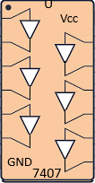
Pin Configuration and Descriptions
The 74LS07 is an 14-pin Dual In-line Package (DIP). Below is the pinout and description:
| Pin Number | Pin Name | Description |
|---|---|---|
| 1 | 1A | Input for Buffer 1 |
| 2 | 1Y | Output for Buffer 1 (open-collector) |
| 3 | 2A | Input for Buffer 2 |
| 4 | 2Y | Output for Buffer 2 (open-collector) |
| 5 | 3A | Input for Buffer 3 |
| 6 | 3Y | Output for Buffer 3 (open-collector) |
| 7 | GND | Ground (0V reference) |
| 8 | 4Y | Output for Buffer 4 (open-collector) |
| 9 | 4A | Input for Buffer 4 |
| 10 | 5Y | Output for Buffer 5 (open-collector) |
| 11 | 5A | Input for Buffer 5 |
| 12 | 6Y | Output for Buffer 6 (open-collector) |
| 13 | 6A | Input for Buffer 6 |
| 14 | Vcc | Positive Supply Voltage (4.75V to 5.25V) |
Usage Instructions
How to Use the 74LS07 in a Circuit
- Power Supply: Connect the Vcc pin (Pin 14) to a regulated 5V power supply and the GND pin (Pin 7) to ground.
- Inputs: Connect the input signals to the respective input pins (1A, 2A, ..., 6A). These inputs are TTL-compatible.
- Outputs: The outputs (1Y, 2Y, ..., 6Y) are open-collector, meaning they require an external pull-up resistor to function properly. Choose a pull-up resistor value based on the desired output voltage and current requirements.
- Driving Loads: The open-collector outputs can drive higher voltage loads (up to 30V) and higher currents (up to 40mA). Ensure the load does not exceed these limits.
- Level Shifting: To use the 74LS07 for level shifting, connect the pull-up resistor to the desired output voltage level.
Important Considerations and Best Practices
- Pull-Up Resistors: Always use pull-up resistors on the outputs. Typical values range from 1kΩ to 10kΩ, depending on the application.
- Output Voltage: The output voltage is determined by the pull-up resistor and the connected load. Ensure the voltage does not exceed 30V.
- Unused Inputs: Tie any unused input pins to ground or Vcc to prevent floating inputs, which can cause erratic behavior.
- Heat Dissipation: If driving multiple high-current loads, ensure proper heat dissipation to avoid exceeding the power dissipation limits.
Example: Interfacing with an Arduino UNO
The following example demonstrates how to use the 74LS07 to drive an LED with an Arduino UNO.
Circuit Setup
- Connect the Vcc pin of the 74LS07 to the 5V pin of the Arduino.
- Connect the GND pin of the 74LS07 to the GND pin of the Arduino.
- Connect an LED and a 330Ω resistor in series between the 1Y output pin and ground.
- Connect the 1A input pin to Arduino digital pin 8.
Arduino Code
// Example code to control an LED using the 74LS07 and Arduino UNO

void setup() {
  pinMode(8, OUTPUT); // Set pin 8 as an output
}

void loop() {
  digitalWrite(8, HIGH); // Turn on the LED
  delay(1000);           // Wait for 1 second
  digitalWrite(8, LOW);  // Turn off the LED
  delay(1000);           // Wait for 1 second
}
Troubleshooting and FAQs
Common Issues and Solutions
No Output Signal:
- Ensure the pull-up resistor is connected to the output pin.
- Verify that the input signal is within the TTL voltage range (0V to 5V).
Output Voltage Too Low:
- Check the value of the pull-up resistor. A lower resistance value may be needed for higher current loads.
- Ensure the load does not exceed the maximum output current (40mA).
Excessive Heat:
- Verify that the total power dissipation does not exceed the component's limits.
- Reduce the number of high-current loads or improve heat dissipation.
Floating Inputs:
- Tie unused input pins to ground or Vcc to prevent erratic behavior.
FAQs
Q: Can the 74LS07 drive a 12V relay?
A: Yes, the 74LS07 can drive a 12V relay, provided the relay's current requirement does not exceed 40mA. Use a pull-up resistor connected to the 12V supply.
Q: What happens if I don't use a pull-up resistor?
A: Without a pull-up resistor, the output will not produce a valid high-level signal, as the open-collector output cannot source current.
Q: Can I use the 74LS07 with a 3.3V logic system?
A: The inputs of the 74LS07 are TTL-compatible and may not reliably detect 3.3V as a high signal. Use a level shifter or a different buffer for 3.3V systems.