Cirkit Designer Logo
Cirkit Designer
Your all-in-one circuit design IDE
Home / 
Component Documentation

How to Use ssd1306 128x32: Examples, Pinouts, and Specs

Image of ssd1306 128x32
Cirkit Designer LogoDesign with ssd1306 128x32 in Cirkit Designer

Introduction

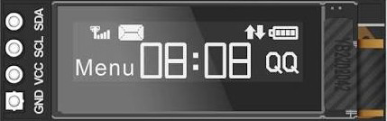
The SSD1306 128x32 is a monochrome OLED display driver manufactured by DSD Tech. It supports a resolution of 128x32 pixels, making it ideal for compact displays in embedded systems. This component is widely used for displaying text, graphics, and simple animations in applications requiring low power consumption and high contrast. Its small form factor and I2C/SPI communication interfaces make it a popular choice for microcontroller-based projects.

Explore Projects Built with ssd1306 128x32

Use Cirkit Designer to design, explore, and prototype these projects online. Some projects support real-time simulation. Click "Open Project" to start designing instantly!
Arduino Nano ESP32-Based Real-Time Clock and OLED Display System
Image of Watch: A project utilizing ssd1306 128x32 in a practical application
This circuit features an Arduino Nano ESP32 microcontroller interfaced with an SSD1306 128x64 SPI OLED display and an RTC DS3231 module. The OLED display is used for visual output, while the RTC module provides accurate timekeeping. The microcontroller coordinates the display and timekeeping functions.
Cirkit Designer LogoOpen Project in Cirkit Designer
Wi-Fi Controlled RGB LED and OLED Display with ESP8266
Image of ESP thermometer reciever: A project utilizing ssd1306 128x32 in a practical application
This circuit features an ESP8266 microcontroller interfaced with a 128x64 OLED display via I2C for visual output and an RGB LED controlled through current-limiting resistors. The ESP8266 provides power and control signals to both the display and the LED, enabling visual feedback and status indication.
Cirkit Designer LogoOpen Project in Cirkit Designer
Arduino Mega 2560-Based Real-Time Clock and Data Logging System with OLED Display
Image of projectwiring: A project utilizing ssd1306 128x32 in a practical application
This circuit features an Arduino Mega 2560 microcontroller interfaced with an OLED display, a DS1307 RTC module, a microSD card breakout, a pushbutton, and a blue LED. The Arduino handles data logging to the microSD card, displays information on the OLED, and reads real-time data from the RTC module, while the pushbutton and LED provide user interaction and status indication.
Cirkit Designer LogoOpen Project in Cirkit Designer
ESP32-Controlled Dual 8x8 LED Matrix Display with NTP Time Synchronization
Image of time: A project utilizing ssd1306 128x32 in a practical application
This circuit features an ESP32 microcontroller connected to two cascaded 8x8 LED matrix displays, powered by a 3.3V battery. The ESP32 drives the displays to show time and other information, with the code indicating functionality for connecting to WiFi, synchronizing time via NTP, and displaying data on the matrices using custom fonts. Additionally, there is a separate 3.3V battery powering a red LED, which appears to function as a simple indicator light.
Cirkit Designer LogoOpen Project in Cirkit Designer

Explore Projects Built with ssd1306 128x32

Use Cirkit Designer to design, explore, and prototype these projects online. Some projects support real-time simulation. Click "Open Project" to start designing instantly!
Image of Watch: A project utilizing ssd1306 128x32 in a practical application
Arduino Nano ESP32-Based Real-Time Clock and OLED Display System
This circuit features an Arduino Nano ESP32 microcontroller interfaced with an SSD1306 128x64 SPI OLED display and an RTC DS3231 module. The OLED display is used for visual output, while the RTC module provides accurate timekeeping. The microcontroller coordinates the display and timekeeping functions.
Cirkit Designer LogoOpen Project in Cirkit Designer
Image of ESP thermometer reciever: A project utilizing ssd1306 128x32 in a practical application
Wi-Fi Controlled RGB LED and OLED Display with ESP8266
This circuit features an ESP8266 microcontroller interfaced with a 128x64 OLED display via I2C for visual output and an RGB LED controlled through current-limiting resistors. The ESP8266 provides power and control signals to both the display and the LED, enabling visual feedback and status indication.
Cirkit Designer LogoOpen Project in Cirkit Designer
Image of projectwiring: A project utilizing ssd1306 128x32 in a practical application
Arduino Mega 2560-Based Real-Time Clock and Data Logging System with OLED Display
This circuit features an Arduino Mega 2560 microcontroller interfaced with an OLED display, a DS1307 RTC module, a microSD card breakout, a pushbutton, and a blue LED. The Arduino handles data logging to the microSD card, displays information on the OLED, and reads real-time data from the RTC module, while the pushbutton and LED provide user interaction and status indication.
Cirkit Designer LogoOpen Project in Cirkit Designer
Image of time: A project utilizing ssd1306 128x32 in a practical application
ESP32-Controlled Dual 8x8 LED Matrix Display with NTP Time Synchronization
This circuit features an ESP32 microcontroller connected to two cascaded 8x8 LED matrix displays, powered by a 3.3V battery. The ESP32 drives the displays to show time and other information, with the code indicating functionality for connecting to WiFi, synchronizing time via NTP, and displaying data on the matrices using custom fonts. Additionally, there is a separate 3.3V battery powering a red LED, which appears to function as a simple indicator light.
Cirkit Designer LogoOpen Project in Cirkit Designer

Common Applications

  • Wearable devices
  • IoT dashboards
  • Portable instruments
  • Embedded system displays
  • Arduino and Raspberry Pi projects

Technical Specifications

Key Technical Details

Parameter Value
Manufacturer DSD Tech
Part ID SSD1306 128x32
Display Type Monochrome OLED
Resolution 128x32 pixels
Communication Interface I2C or SPI
Operating Voltage 3.3V to 5V
Current Consumption ~20mA (typical)
Pixel Color White
Dimensions ~22mm x 11mm

Pin Configuration (I2C Mode)

Pin Name Pin Number Description
GND 1 Ground
VCC 2 Power supply (3.3V or 5V)
SCL 3 Serial Clock Line (I2C)
SDA 4 Serial Data Line (I2C)

Pin Configuration (SPI Mode)

Pin Name Pin Number Description
GND 1 Ground
VCC 2 Power supply (3.3V or 5V)
SCK 3 Serial Clock (SPI)
MOSI 4 Master Out Slave In (SPI)
CS 5 Chip Select (SPI)
DC 6 Data/Command Control
RES 7 Reset

Usage Instructions

Connecting the SSD1306 128x32 to an Arduino UNO (I2C Mode)

  1. Wiring:

    • Connect the GND pin of the display to the GND pin of the Arduino.
    • Connect the VCC pin of the display to the 5V pin of the Arduino.
    • Connect the SCL pin of the display to the A5 pin of the Arduino (I2C clock).
    • Connect the SDA pin of the display to the A4 pin of the Arduino (I2C data).
  2. Install Required Libraries:

    • Install the Adafruit_GFX and Adafruit_SSD1306 libraries from the Arduino Library Manager.
  3. Example Code: Below is an example sketch to display "Hello, World!" on the SSD1306 128x32 display:

    #include <Wire.h>
    #include <Adafruit_GFX.h>
    #include <Adafruit_SSD1306.h>
    
    // Define the screen dimensions
    #define SCREEN_WIDTH 128
    #define SCREEN_HEIGHT 32
    
    // Create an SSD1306 object with I2C address 0x3C
    Adafruit_SSD1306 display(SCREEN_WIDTH, SCREEN_HEIGHT, &Wire, -1);
    
    void setup() {
      // Initialize the display
      if (!display.begin(SSD1306_I2C_ADDRESS, 0x3C)) {
        // If initialization fails, print an error message
        Serial.println(F("SSD1306 allocation failed"));
        for (;;); // Halt execution
      }
    
      // Clear the display buffer
      display.clearDisplay();
    
      // Set text size and color
      display.setTextSize(1); // Text size multiplier
      display.setTextColor(SSD1306_WHITE);
    
      // Set cursor position
      display.setCursor(0, 0);
    
      // Print text to the display buffer
      display.println(F("Hello, World!"));
    
      // Display the buffer content on the screen
      display.display();
    }
    
    void loop() {
      // Nothing to do here
    }
    

Important Considerations

  • Ensure the I2C address of the display matches the one in your code (default is 0x3C).
  • Use pull-up resistors (4.7kΩ to 10kΩ) on the SDA and SCL lines if communication issues occur.
  • Avoid exceeding the operating voltage range (3.3V to 5V) to prevent damage to the display.
  • For SPI mode, ensure proper configuration of the CS, DC, and RES pins in your code.

Troubleshooting and FAQs

Common Issues

  1. Display Not Turning On:

    • Verify the wiring connections, especially the power (VCC and GND) pins.
    • Ensure the correct I2C address (0x3C or 0x3D) is used in the code.
  2. Flickering or Corrupted Display:

    • Check for loose connections on the SDA and SCL lines.
    • Use shorter wires to reduce noise in the I2C communication.
  3. Library Errors During Compilation:

    • Ensure the Adafruit_GFX and Adafruit_SSD1306 libraries are installed and up to date.
    • Restart the Arduino IDE after installing the libraries.
  4. Blank Screen After Uploading Code:

    • Confirm that the display dimensions (128x32) are correctly defined in the code.
    • Check the power supply voltage and current to ensure it meets the display's requirements.

FAQs

Q: Can I use the SSD1306 128x32 with a Raspberry Pi?
A: Yes, the SSD1306 128x32 is compatible with Raspberry Pi. You can use libraries like luma.oled in Python to control the display.

Q: What is the maximum refresh rate of the display?
A: The SSD1306 supports a refresh rate of up to 100Hz, depending on the communication interface and configuration.

Q: Can I daisy-chain multiple SSD1306 displays?
A: No, the SSD1306 does not support daisy-chaining. However, you can use multiple displays with different I2C addresses or separate SPI chip select lines.

Q: Is the display sunlight-readable?
A: The SSD1306 128x32 is not designed for direct sunlight readability due to its limited brightness. It is best suited for indoor or shaded environments.