Cirkit Designer
Your all-in-one circuit design IDE
Home /
Component Documentation
How to Use reealy: Examples, Pinouts, and Specs
Introduction
- The "Reealy" is a fictional electronic component, which could represent a placeholder for a real-world device or a misspelling of an existing component. For the purpose of this documentation, we will treat it as a generic electronic module with undefined functionality.
- Common applications and use cases for the Reealy component are speculative but could include general-purpose signal processing, interfacing, or control in electronic circuits.
Explore Projects Built with reealy
Arduino UNO-Based Real-Time Clock with Alarm and LCD Display
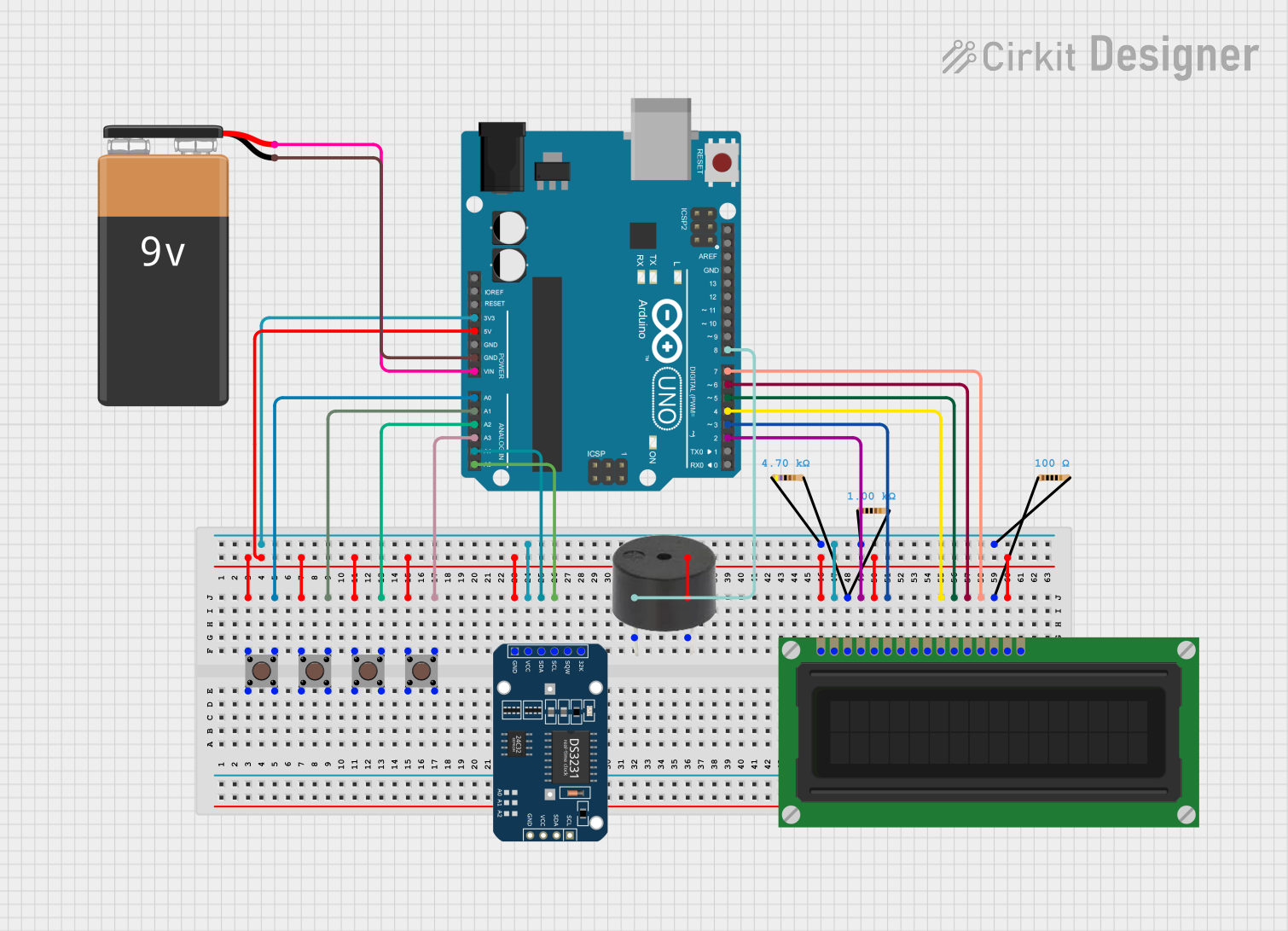
This circuit is a real-time clock with an alarm feature, utilizing an Arduino UNO, an LCD display, a DS3231 RTC module, and multiple pushbuttons for user input. The Arduino controls the display and alarm functions, while the RTC module provides accurate timekeeping. The circuit also includes a buzzer for alarm notifications and resistors for proper voltage regulation.
Arduino UNO-Based Real-Time Clock with I2C LCD Display and IO Expansion

This circuit is an Arduino-based real-time clock and display system. It uses an Arduino UNO to interface with a DS1307 RTC module for timekeeping and a 20x4 I2C LCD to display the current time and date. Additionally, a PCF8574 IO Expansion Board is used to extend the I2C bus for additional I/O operations.
Arduino-Based Real-Time Clock and I2C LCD Display System
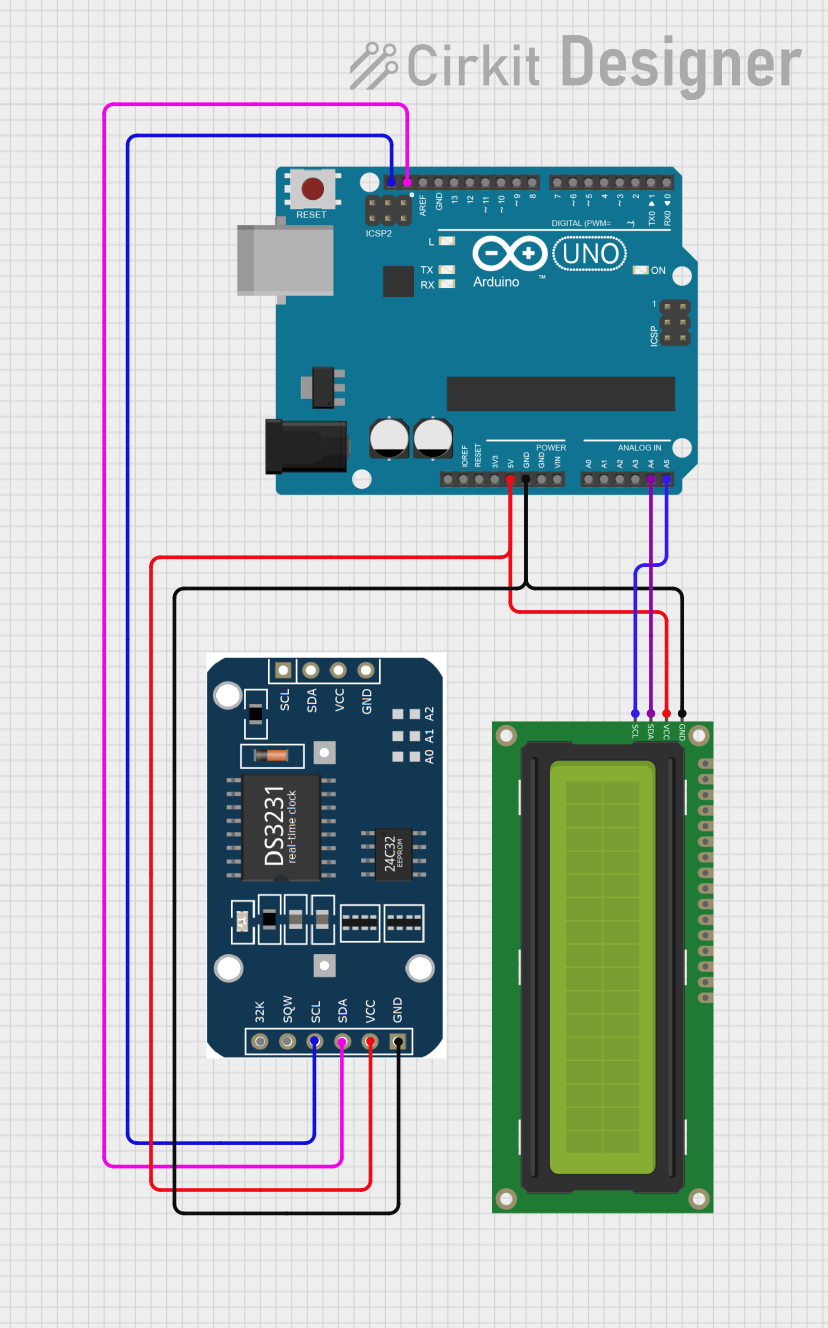
This circuit consists of an Arduino UNO connected to an RTC module and a 16x2 I2C LCD display. The Arduino UNO reads the real-time clock data from the RTC module and displays it on the LCD screen via I2C communication.
Arduino Nano Based Real-Time Clock Display with TM1637

This circuit features an Arduino Nano interfacing with a DS3231 Real-Time Clock for timekeeping and a TM1637 display module for visual output. The Arduino facilitates I2C communication with the RTC and controls the display using digital IO, serving as the central processing unit for a digital clock or timer application.
Explore Projects Built with reealy
Arduino UNO-Based Real-Time Clock with Alarm and LCD Display
This circuit is a real-time clock with an alarm feature, utilizing an Arduino UNO, an LCD display, a DS3231 RTC module, and multiple pushbuttons for user input. The Arduino controls the display and alarm functions, while the RTC module provides accurate timekeeping. The circuit also includes a buzzer for alarm notifications and resistors for proper voltage regulation.
Arduino UNO-Based Real-Time Clock with I2C LCD Display and IO Expansion
This circuit is an Arduino-based real-time clock and display system. It uses an Arduino UNO to interface with a DS1307 RTC module for timekeeping and a 20x4 I2C LCD to display the current time and date. Additionally, a PCF8574 IO Expansion Board is used to extend the I2C bus for additional I/O operations.
Arduino-Based Real-Time Clock and I2C LCD Display System
This circuit consists of an Arduino UNO connected to an RTC module and a 16x2 I2C LCD display. The Arduino UNO reads the real-time clock data from the RTC module and displays it on the LCD screen via I2C communication.
Arduino Nano Based Real-Time Clock Display with TM1637
This circuit features an Arduino Nano interfacing with a DS3231 Real-Time Clock for timekeeping and a TM1637 display module for visual output. The Arduino facilitates I2C communication with the RTC and controls the display using digital IO, serving as the central processing unit for a digital clock or timer application.
Technical Specifications
Since the Reealy component is fictional, the following specifications are hypothetical and provided for illustrative purposes:
| Parameter | Value | Description |
|---|---|---|
| Operating Voltage | 3.3V - 5V | Voltage range for safe operation |
| Current Rating | 50mA | Maximum current the component can draw |
| Power Rating | 0.25W | Maximum power dissipation |
| Communication | I2C or SPI (hypothetical) | Interface for data communication |
Pin Configuration
Below is a hypothetical pin configuration for the Reealy component:
| Pin Number | Pin Name | Description |
|---|---|---|
| 1 | VCC | Power supply input (3.3V - 5V) |
| 2 | GND | Ground connection |
| 3 | SDA | Data line for I2C communication |
| 4 | SCL | Clock line for I2C communication |
| 5 | CS | Chip Select for SPI communication |
| 6 | MOSI | Master Out Slave In (SPI data line) |
| 7 | MISO | Master In Slave Out (SPI data line) |
| 8 | INT | Interrupt output for signaling events |
Usage Instructions
How to Use the Reealy Component in a Circuit
- Power Supply: Connect the VCC pin to a 3.3V or 5V power source and the GND pin to the ground of your circuit.
- Communication Interface: Depending on your application, use either the I2C (SDA and SCL pins) or SPI (CS, MOSI, MISO, and SCL pins) interface to communicate with the Reealy component.
- Interrupt Handling: If the component generates interrupts, connect the INT pin to a microcontroller's interrupt-capable pin.
Important Considerations and Best Practices
- Ensure the power supply voltage does not exceed the specified range to avoid damaging the component.
- Use appropriate pull-up resistors for the I2C lines (SDA and SCL) if they are not internally provided by the Reealy component.
- For SPI communication, ensure proper configuration of the microcontroller's SPI settings (e.g., clock polarity and phase).
- Decouple the power supply with a 0.1µF capacitor close to the VCC pin to reduce noise.
Example Code for Arduino UNO
Below is an example of how to interface the Reealy component with an Arduino UNO using the I2C protocol:
#include <Wire.h> // Include the Wire library for I2C communication

#define REEALY_ADDRESS 0x50 // Hypothetical I2C address of the Reealy component

void setup() {
  Wire.begin(); // Initialize I2C communication
  Serial.begin(9600); // Start serial communication for debugging
  Serial.println("Initializing Reealy component...");

  // Hypothetical initialization sequence
  Wire.beginTransmission(REEALY_ADDRESS);
  Wire.write(0x01); // Send a command to initialize the component
  Wire.endTransmission();
  Serial.println("Reealy initialized.");
}

void loop() {
  Wire.beginTransmission(REEALY_ADDRESS);
  Wire.write(0x02); // Hypothetical command to request data
  Wire.endTransmission();

  Wire.requestFrom(REEALY_ADDRESS, 1); // Request 1 byte of data
  if (Wire.available()) {
    int data = Wire.read(); // Read the received data
    Serial.print("Received data: ");
    Serial.println(data);
  }

  delay(1000); // Wait for 1 second before the next request
}
Troubleshooting and FAQs
Common Issues
No Communication with the Component:
- Ensure the correct I2C or SPI pins are connected.
- Verify the component's address or SPI settings.
- Check for loose or incorrect wiring.
Overheating:
- Confirm that the power supply voltage is within the specified range.
- Check for short circuits in the wiring.
No Data Received:
- Ensure the component is properly initialized.
- Verify that the microcontroller is configured correctly for the chosen communication protocol.
Solutions and Tips for Troubleshooting
- Use a multimeter to check the voltage levels at the VCC and GND pins.
- Use an oscilloscope or logic analyzer to monitor the I2C or SPI signals for proper communication.
- Double-check the datasheet (if available) for any additional configuration requirements.
This documentation is based on a fictional component and is intended for illustrative purposes only.