How to Use Terminal Sensor Adapter: Examples, Pinouts, and Specs
Introduction
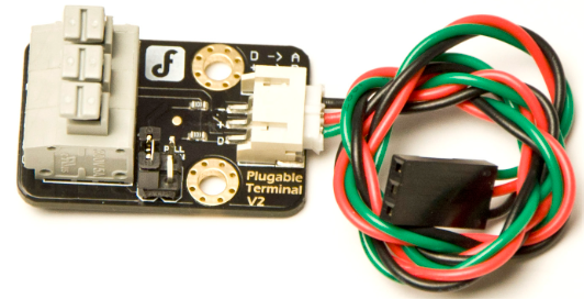
The Terminal Sensor Adapter (Manufacturer Part ID: DFR0055) by DFROBOT is a versatile device designed to connect sensors to a terminal or control system. It facilitates the seamless transmission of sensor data and ensures reliable communication between sensors and processing units. This adapter simplifies the integration of sensors into various electronic systems, making it an essential tool for prototyping, development, and deployment in IoT, robotics, and automation projects.
Explore Projects Built with Terminal Sensor Adapter


Explore Projects Built with Terminal Sensor Adapter
Common Applications and Use Cases
- Connecting analog or digital sensors to microcontrollers or control systems.
- Prototyping sensor-based projects in IoT and robotics.
- Simplifying wiring and reducing errors in sensor connections.
- Educational projects for learning sensor interfacing and data acquisition.
Technical Specifications
The following table outlines the key technical details of the Terminal Sensor Adapter:
| Parameter | Specification |
|---|---|
| Manufacturer | DFRobot |
| Part ID | DFR0055 |
| Input Voltage | 3.3V or 5V (compatible with most microcontrollers) |
| Output Signal | Analog or Digital (depending on the connected sensor) |
| Connector Type | Screw terminal and 3-pin sensor interface |
| Dimensions | 42mm x 32mm |
| Mounting | PCB-compatible with mounting holes |
Pin Configuration and Descriptions
The Terminal Sensor Adapter features a 3-pin interface for sensor connections and screw terminals for secure wiring. Below is the pin configuration:
| Pin | Label | Description |
|---|---|---|
| 1 | VCC | Power supply input (3.3V or 5V) for the connected sensor. |
| 2 | GND | Ground connection for the sensor. |
| 3 | SIG | Signal pin for transmitting sensor data (analog/digital). |
Usage Instructions
How to Use the Terminal Sensor Adapter in a Circuit
- Connect the Sensor: Attach the sensor to the 3-pin interface on the adapter. Ensure the VCC, GND, and SIG pins are correctly aligned.
- Secure Wiring: Use the screw terminals to connect the adapter to your microcontroller or control system. Tighten the screws to ensure a stable connection.
- Power the Adapter: Supply 3.3V or 5V to the VCC pin, depending on the sensor's requirements.
- Read Sensor Data: Use the SIG pin to read the sensor's output signal. This can be analog or digital, depending on the sensor type.
Important Considerations and Best Practices
- Voltage Compatibility: Ensure the sensor and microcontroller operate at the same voltage level (3.3V or 5V).
- Signal Type: Verify whether the sensor outputs an analog or digital signal and configure your microcontroller accordingly.
- Secure Connections: Double-check all connections to avoid loose wires, which can cause unreliable data transmission.
- Avoid Overloading: Do not exceed the current or voltage ratings of the adapter or connected components.
Example: Connecting to an Arduino UNO
Below is an example of how to use the Terminal Sensor Adapter with an Arduino UNO to read data from an analog temperature sensor.
Circuit Diagram
- Connect the sensor to the adapter's 3-pin interface.
- Use the screw terminals to connect:
- VCC to the Arduino's 5V pin.
- GND to the Arduino's GND pin.
- SIG to the Arduino's A0 pin.
Arduino Code
// Example code to read data from a sensor connected via the Terminal Sensor Adapter
// Ensure the sensor outputs an analog signal and is connected to pin A0.

const int sensorPin = A0; // Define the analog pin connected to the SIG pin
int sensorValue = 0;      // Variable to store the sensor reading

void setup() {
  Serial.begin(9600); // Initialize serial communication at 9600 baud
}

void loop() {
  sensorValue = analogRead(sensorPin); // Read the analog value from the sensor
  Serial.print("Sensor Value: ");      // Print the sensor value to the Serial Monitor
  Serial.println(sensorValue);
  delay(500); // Wait for 500ms before the next reading
}
Troubleshooting and FAQs
Common Issues and Solutions
No Sensor Data Output
- Cause: Incorrect wiring or loose connections.
- Solution: Double-check all connections, ensuring the VCC, GND, and SIG pins are correctly aligned and securely connected.
Inconsistent Readings
- Cause: Electrical noise or unstable power supply.
- Solution: Use a decoupling capacitor between VCC and GND to stabilize the power supply.
Sensor Not Detected by Microcontroller
- Cause: Voltage mismatch between the sensor and microcontroller.
- Solution: Verify that the sensor and microcontroller operate at the same voltage level (3.3V or 5V).
Overheating
- Cause: Exceeding the current or voltage ratings of the adapter.
- Solution: Ensure the connected sensor and power supply are within the adapter's specifications.
FAQs
Q: Can I use this adapter with digital sensors?
A: Yes, the adapter supports both analog and digital sensors. Ensure the SIG pin is connected to a digital input pin on your microcontroller for digital sensors.Q: Is the adapter compatible with Raspberry Pi?
A: Yes, the adapter can be used with Raspberry Pi. However, ensure proper voltage level shifting if the sensor operates at 5V, as Raspberry Pi GPIO pins are 3.3V tolerant.Q: Can I connect multiple sensors to one adapter?
A: No, the adapter is designed for a single sensor connection. Use additional adapters for multiple sensors.
This documentation provides a comprehensive guide to using the DFRobot Terminal Sensor Adapter (DFR0055). For further assistance, refer to the manufacturer's website or contact technical support.