How to Use PiggyMeter: Examples, Pinouts, and Specs
Introduction
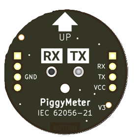
The PiggyMeter, manufactured by Aquaticus (Part ID: IEC62056-21 Optical Interface), is an advanced electronic measuring device designed to monitor and display electrical parameters such as current, voltage, and power consumption. This device is particularly useful for energy efficiency assessments, enabling users to track and optimize power usage in various applications. Its compact design and precise measurement capabilities make it a versatile tool for both industrial and residential use.
Explore Projects Built with PiggyMeter
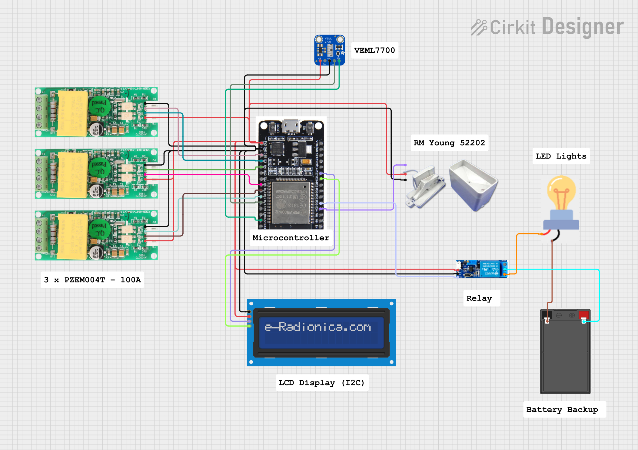
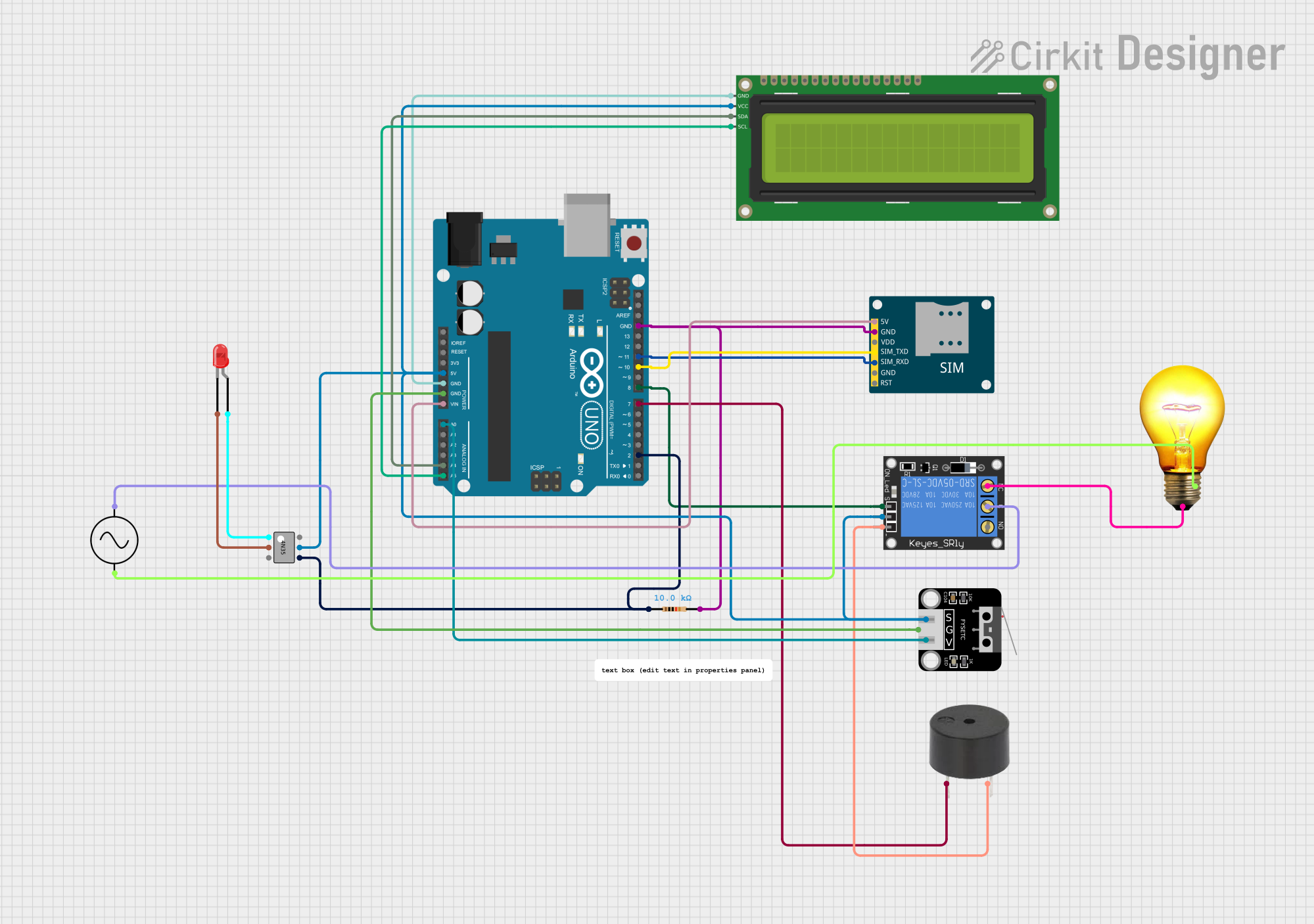
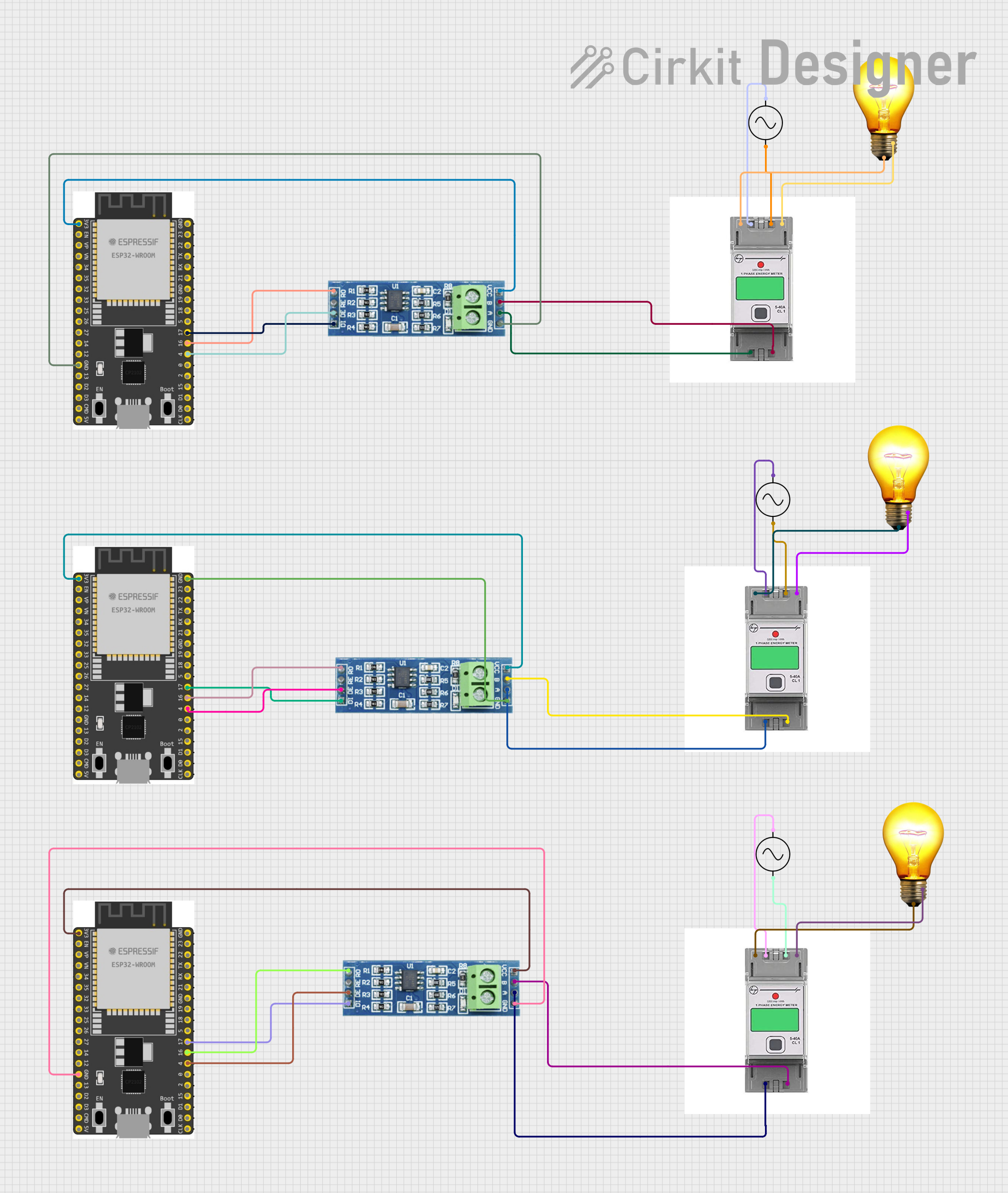

Explore Projects Built with PiggyMeter
Common Applications and Use Cases
- Monitoring energy consumption in residential and commercial buildings.
- Evaluating the efficiency of electrical appliances and systems.
- Integrating into smart home systems for real-time energy tracking.
- Industrial power monitoring for machinery and equipment.
- Educational purposes in electronics and electrical engineering labs.
Technical Specifications
The PiggyMeter is designed to provide accurate and reliable measurements while being easy to integrate into existing systems. Below are its key technical specifications:
General Specifications
| Parameter | Value |
|---|---|
| Manufacturer | Aquaticus |
| Part ID | IEC62056-21 Optical Interface |
| Measurement Parameters | Voltage, Current, Power |
| Operating Voltage Range | 3.3V to 5V DC |
| Measurement Accuracy | ±0.5% |
| Communication Protocol | IEC 62056-21 (Optical) |
| Operating Temperature | -10°C to 50°C |
| Dimensions | 50mm x 30mm x 15mm |
Pin Configuration
The PiggyMeter features a simple pinout for easy integration into circuits. Below is the pin configuration:
| Pin Number | Pin Name | Description |
|---|---|---|
| 1 | VCC | Power supply input (3.3V to 5V DC) |
| 2 | GND | Ground connection |
| 3 | TX | Transmit data (IEC 62056-21 protocol) |
| 4 | RX | Receive data (IEC 62056-21 protocol) |
| 5 | OPTICAL_IN | Optical input for data reception |
| 6 | OPTICAL_OUT | Optical output for data transmission |
Usage Instructions
The PiggyMeter is designed for straightforward integration into electrical systems. Follow the steps below to use the device effectively:
Connecting the PiggyMeter
- Power Supply: Connect the VCC pin to a 3.3V or 5V DC power source and the GND pin to the ground.
- Data Communication: Use the TX and RX pins to interface with a microcontroller or computer. Ensure the device supports the IEC 62056-21 protocol.
- Optical Interface: For optical communication, align the OPTICAL_IN and OPTICAL_OUT ports with the corresponding optical transceivers.
Important Considerations
- Ensure the power supply voltage is within the specified range (3.3V to 5V DC) to avoid damage to the device.
- Use appropriate pull-up resistors on the TX and RX lines if required by your microcontroller.
- Avoid exposing the device to temperatures outside the operating range (-10°C to 50°C).
- For accurate measurements, ensure proper alignment of the optical interface.
Example: Using PiggyMeter with Arduino UNO
The PiggyMeter can be easily connected to an Arduino UNO for data acquisition. Below is an example code snippet to read data from the PiggyMeter:
#include <SoftwareSerial.h>

// Define RX and TX pins for SoftwareSerial
#define RX_PIN 10  // Connect to PiggyMeter TX pin
#define TX_PIN 11  // Connect to PiggyMeter RX pin

SoftwareSerial piggyMeterSerial(RX_PIN, TX_PIN);

void setup() {
  Serial.begin(9600); // Initialize Serial Monitor
  piggyMeterSerial.begin(9600); // Initialize PiggyMeter communication

  Serial.println("PiggyMeter Initialized");
}

void loop() {
  if (piggyMeterSerial.available()) {
    // Read data from PiggyMeter
    String data = piggyMeterSerial.readStringUntil('\n');
    Serial.println("PiggyMeter Data: " + data); // Print data to Serial Monitor
  }
}
Notes:
- Ensure the PiggyMeter is properly powered and connected to the Arduino.
- The IEC 62056-21 protocol may require additional parsing depending on the data format.
Troubleshooting and FAQs
Common Issues and Solutions
No Data Output:
- Cause: Incorrect wiring or loose connections.
- Solution: Verify all connections, especially the TX and RX pins.
Inaccurate Measurements:
- Cause: Misalignment of the optical interface or external interference.
- Solution: Ensure proper alignment of the optical ports and minimize external light interference.
Device Not Powering On:
- Cause: Insufficient power supply or incorrect voltage.
- Solution: Check the power supply voltage and ensure it is within the 3.3V to 5V range.
Communication Errors:
- Cause: Baud rate mismatch or protocol incompatibility.
- Solution: Ensure the baud rate is set to 9600 and the device supports IEC 62056-21.
FAQs
Q1: Can the PiggyMeter be used outdoors?
A1: The PiggyMeter is not weatherproof and should be used in a dry, indoor environment.
Q2: What is the maximum distance for optical communication?
A2: The maximum distance depends on the optical transceivers used, but typically it is up to 1 meter.
Q3: Is the PiggyMeter compatible with other microcontrollers?
A3: Yes, the PiggyMeter can be used with any microcontroller that supports the IEC 62056-21 protocol.
Q4: How do I reset the PiggyMeter?
A4: Power cycle the device by disconnecting and reconnecting the power supply.
By following this documentation, users can effectively integrate and utilize the PiggyMeter for accurate energy monitoring and analysis.