How to Use Potentiometer audio: Examples, Pinouts, and Specs
Introduction
A potentiometer audio is a variable resistor designed specifically for adjusting audio levels. It allows users to control volume, tone, or balance in audio equipment by varying the resistance in a circuit. This component is widely used in audio amplifiers, mixers, and other sound systems to provide precise control over sound output.
Explore Projects Built with Potentiometer audio
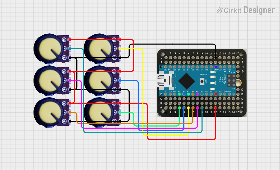
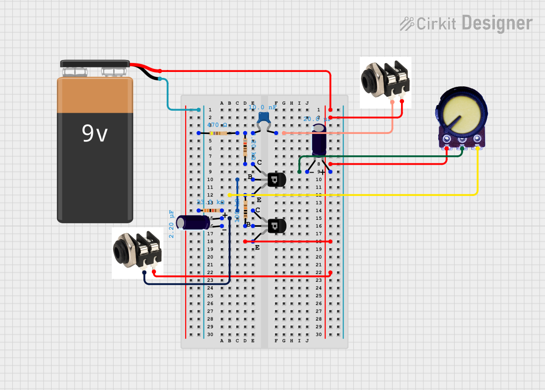
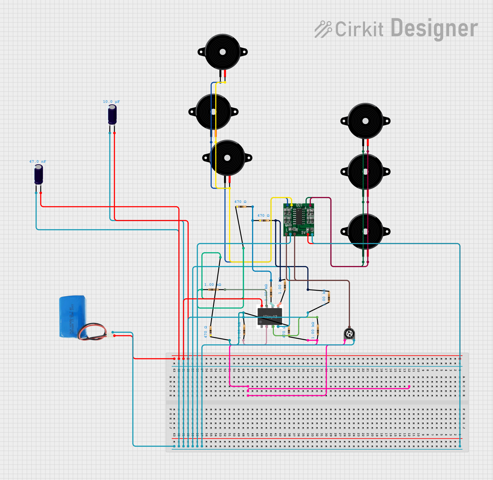
Explore Projects Built with Potentiometer audio
Common Applications and Use Cases
- Volume control in audio amplifiers and speakers
- Tone adjustment in equalizers
- Balance control in stereo systems
- Signal attenuation in audio mixers
- DIY audio projects and custom sound systems
Technical Specifications
Below are the key technical details for a standard potentiometer audio component:
| Parameter | Specification |
|---|---|
| Resistance Range | 1 kΩ to 1 MΩ |
| Taper Type | Linear (B) or Logarithmic (A) |
| Power Rating | 0.1 W to 0.5 W |
| Maximum Voltage | 50 V DC |
| Operating Temperature | -10°C to +70°C |
| Shaft Type | Knurled or smooth |
| Rotation Angle | 270° (typical) |
| Mounting Type | Through-hole or panel mount |
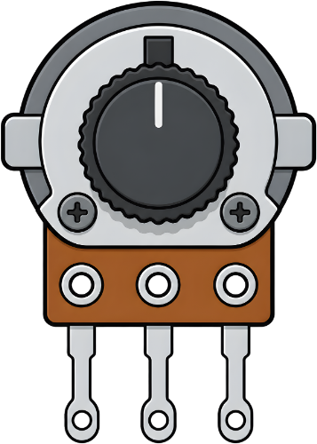
Pin Configuration and Descriptions
A potentiometer audio typically has three pins:
| Pin | Description |
|---|---|
| Pin 1 | Connects to one end of the resistive track |
| Pin 2 | Wiper (variable output) - provides the adjustable voltage |
| Pin 3 | Connects to the other end of the resistive track |
Usage Instructions
How to Use the Component in a Circuit
- Identify the Pins: Locate the three pins on the potentiometer. Pin 1 and Pin 3 are connected to the ends of the resistive track, while Pin 2 is the wiper.
- Connect the Circuit:
- Connect Pin 1 to the ground (GND) of your circuit.
- Connect Pin 3 to the input voltage or audio signal.
- Connect Pin 2 to the output where the adjusted signal is required.
- Adjust the Resistance: Rotate the potentiometer's shaft to vary the resistance and adjust the audio level.
Important Considerations and Best Practices
- Taper Type: Use a logarithmic taper (A) for volume control, as it matches the human ear's perception of sound.
- Power Rating: Ensure the potentiometer's power rating is sufficient for your application to avoid overheating.
- Debouncing: If used in digital circuits, consider adding a capacitor to reduce noise caused by mechanical movement.
- Mounting: Secure the potentiometer firmly to prevent accidental movement or damage.
Example: Connecting to an Arduino UNO
Below is an example of using a potentiometer audio to control the brightness of an LED, simulating volume control.
// Arduino example: Using a potentiometer to control LED brightness
const int potPin = A0;  // Potentiometer connected to analog pin A0
const int ledPin = 9;   // LED connected to digital pin 9 (PWM)

void setup() {
  pinMode(ledPin, OUTPUT);  // Set LED pin as output
}

void loop() {
  int potValue = analogRead(potPin);  // Read potentiometer value (0-1023)
  int ledBrightness = map(potValue, 0, 1023, 0, 255);
  // Map pot value to PWM range (0-255)

  analogWrite(ledPin, ledBrightness);  // Set LED brightness
  delay(10);  // Small delay for stability
}
Troubleshooting and FAQs
Common Issues Users Might Face
No Change in Output:
- Cause: Incorrect wiring of the potentiometer pins.
- Solution: Verify the connections. Ensure Pin 1 is connected to GND, Pin 3 to the input signal, and Pin 2 to the output.
Noise or Crackling Sound:
- Cause: Dust or wear on the resistive track.
- Solution: Clean the potentiometer with contact cleaner or replace it if worn out.
Overheating:
- Cause: Exceeding the power rating of the potentiometer.
- Solution: Use a potentiometer with a higher power rating or reduce the current in the circuit.
Inconsistent Adjustment:
- Cause: Loose mounting or damaged shaft.
- Solution: Secure the potentiometer properly and check for physical damage.
FAQs
Q: Can I use a linear taper potentiometer for volume control?
A: While it is possible, a logarithmic taper is recommended for volume control as it provides a more natural adjustment curve for audio levels.
Q: How do I know the resistance value of my potentiometer?
A: The resistance value is usually printed on the body of the potentiometer (e.g., "10k" for 10 kΩ).
Q: Can I use a potentiometer audio for non-audio applications?
A: Yes, it can be used in any circuit requiring variable resistance, such as dimming LEDs or adjusting sensor sensitivity.
Q: What is the difference between a potentiometer and a rheostat?
A: A potentiometer has three pins and is used as a voltage divider, while a rheostat has two pins and is used to control current.