How to Use PLC FX3U: Examples, Pinouts, and Specs
Introduction
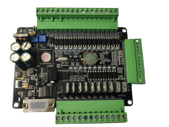
The PLC FX3U is a programmable logic controller (PLC) developed by Mitsubishi Electric. It is designed for automation and control applications in industrial environments. The FX3U series is known for its modular design, high-speed processing capabilities, and extensive I/O options, making it ideal for managing complex industrial tasks. It supports advanced communication protocols and can be expanded with additional modules to meet specific application requirements.
Explore Projects Built with PLC FX3U


Explore Projects Built with PLC FX3U
Common Applications and Use Cases
- Factory automation and process control
- Conveyor belt systems
- Packaging machinery
- HVAC (Heating, Ventilation, and Air Conditioning) systems
- Water treatment plants
- Energy management systems
Technical Specifications
Key Technical Details
| Parameter | Specification |
|---|---|
| Power Supply Voltage | 100-240V AC or 24V DC |
| Processing Speed | 0.065 µs per instruction |
| Program Memory | 64,000 steps |
| I/O Points | Up to 384 (with expansion modules) |
| Communication Interfaces | RS-232, RS-485, Ethernet (via modules) |
| Analog I/O | Supported via expansion modules |
| Operating Temperature | 0°C to 55°C |
| Storage Temperature | -25°C to 75°C |
| Dimensions (Base Unit) | Varies by model (e.g., FX3U-32MR: 90x86x75 mm) |
| Certifications | CE, UL, cUL |
Pin Configuration and Descriptions
The FX3U base unit includes a variety of input and output terminals. Below is an example pin configuration for the FX3U-32MR model:
Input Terminals
| Pin Number | Label | Description |
|---|---|---|
| X0-X15 | Inputs | Digital input terminals (16) |
| COM | Common | Common terminal for inputs |
Output Terminals
| Pin Number | Label | Description |
|---|---|---|
| Y0-Y15 | Outputs | Digital output terminals (16) |
| COM | Common | Common terminal for outputs |
Power Terminals
| Pin Number | Label | Description |
|---|---|---|
| L, N | AC Power | Connect to 100-240V AC supply |
| +24V, 0V | DC Power | 24V DC output for sensors |
Usage Instructions
How to Use the PLC FX3U in a Circuit
- Power Connection: Connect the power supply to the L and N terminals for AC power or to the +24V and 0V terminals for DC power.
- Input Connections: Wire sensors or switches to the input terminals (X0-X15). Ensure the common terminal (COM) is properly connected.
- Output Connections: Connect actuators, relays, or other devices to the output terminals (Y0-Y15). Use the corresponding common terminal (COM).
- Programming: Use Mitsubishi's GX Works2 or GX Developer software to write and upload ladder logic programs to the PLC.
- Communication: If required, connect communication modules (e.g., Ethernet or RS-485) to enable data exchange with other devices or systems.
Important Considerations and Best Practices
- Power Supply: Ensure the power supply voltage matches the PLC's specifications to avoid damage.
- Grounding: Properly ground the PLC to reduce electrical noise and improve reliability.
- Expansion Modules: When adding expansion modules, ensure compatibility with the FX3U series and follow the manufacturer's installation guidelines.
- Programming: Test ladder logic programs in simulation mode before deploying them to the PLC.
- Maintenance: Regularly inspect wiring and connections to prevent loose terminals or corrosion.
Example Code for Arduino Communication
The FX3U can communicate with an Arduino UNO via RS-232 or RS-485. Below is an example of Arduino code for sending data to the PLC using RS-485:
#include <SoftwareSerial.h>

// Define RS-485 communication pins
#define RX_PIN 10  // Arduino RX pin
#define TX_PIN 11  // Arduino TX pin
#define DE_PIN 2   // Driver Enable pin for RS-485 module

SoftwareSerial rs485(TX_PIN, RX_PIN);

void setup() {
  pinMode(DE_PIN, OUTPUT);
  digitalWrite(DE_PIN, LOW); // Set RS-485 to receive mode
  rs485.begin(9600);         // Initialize RS-485 communication at 9600 baud
  Serial.begin(9600);        // Initialize Serial Monitor for debugging
}

void loop() {
  // Example: Send a command to the PLC
  digitalWrite(DE_PIN, HIGH); // Set RS-485 to transmit mode
  rs485.write("Hello PLC");   // Send data to the PLC
  delay(10);                  // Wait for transmission to complete
  digitalWrite(DE_PIN, LOW);  // Set RS-485 back to receive mode

  // Example: Read response from the PLC
  if (rs485.available()) {
    String response = "";
    while (rs485.available()) {
      response += (char)rs485.read();
    }
    Serial.println("PLC Response: " + response);
  }

  delay(1000); // Wait before sending the next command
}
Notes:
- Use an RS-485 module (e.g., MAX485) to interface between the Arduino and the PLC.
- Ensure the baud rate and communication settings match those configured in the PLC.
Troubleshooting and FAQs
Common Issues and Solutions
PLC Not Powering On
- Cause: Incorrect power supply voltage or loose connections.
- Solution: Verify the power supply voltage and ensure all connections are secure.
Inputs Not Responding
- Cause: Faulty wiring or incorrect sensor configuration.
- Solution: Check the wiring and ensure the sensors are compatible with the PLC.
Outputs Not Activating
- Cause: Overloaded output terminals or incorrect wiring.
- Solution: Verify the load connected to the outputs and ensure proper wiring.
Communication Failure
- Cause: Incorrect communication settings or faulty cables.
- Solution: Check the baud rate, parity, and other communication parameters. Replace damaged cables if necessary.
FAQs
Can the FX3U be programmed using a USB cable?
- Yes, the FX3U can be programmed using a USB-to-RS-232 or USB-to-MiniDIN cable with the appropriate driver installed.
What is the maximum number of expansion modules supported?
- The FX3U supports up to 8 expansion modules, depending on the model and configuration.
Is the FX3U compatible with SCADA systems?
- Yes, the FX3U can communicate with SCADA systems via supported communication protocols like Modbus or Ethernet (with additional modules).
Can the FX3U handle analog inputs and outputs?
- Yes, analog I/O is supported through dedicated expansion modules.
By following this documentation, users can effectively utilize the PLC FX3U for a wide range of industrial automation tasks.