How to Use Step-Down Voltage Regulator : Examples, Pinouts, and Specs
Introduction
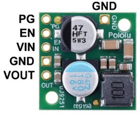
The Pololu D24V22F5 Step-Down Voltage Regulator is a compact and efficient device designed to reduce an input voltage to a stable, lower output voltage of 5V. This regulator is based on a synchronous buck converter design, ensuring high efficiency and minimal heat generation. It is ideal for powering low-voltage devices from higher-voltage sources, such as batteries or power adapters.
Explore Projects Built with Step-Down Voltage Regulator


Explore Projects Built with Step-Down Voltage Regulator
Common Applications and Use Cases
- Powering microcontrollers (e.g., Arduino, Raspberry Pi) from higher-voltage sources.
- Supplying stable 5V power to sensors, modules, and other electronic components.
- Battery-powered projects requiring efficient voltage regulation.
- Robotics and embedded systems with mixed-voltage requirements.
Technical Specifications
The following table outlines the key technical details of the Pololu D24V22F5 Step-Down Voltage Regulator:
| Parameter | Value |
|---|---|
| Input Voltage Range | 6V to 38V |
| Output Voltage | 5V (fixed) |
| Maximum Output Current | 2.5A |
| Efficiency | Up to 95% (depending on input voltage and load) |
| Quiescent Current | <1 mA |
| Switching Frequency | ~500 kHz |
| Dimensions | 0.7" × 0.8" × 0.3" (18 mm × 20 mm × 8 mm) |
| Weight | 1.5 g |
| Operating Temperature | -40°C to +85°C |
| Protection Features | Over-current, over-temperature, and short-circuit protection |
Pin Configuration and Descriptions
The Pololu D24V22F5 has six pins, as described in the table below:
| Pin | Name | Description |
|---|---|---|
| 1 | VIN | Input voltage pin (6V to 38V). Connect to the positive terminal of the power source. |
| 2 | GND | Ground pin. Connect to the negative terminal of the power source. |
| 3 | VOUT | Regulated 5V output pin. Connect to the load requiring 5V. |
| 4 | GND | Additional ground pin for improved connection. |
| 5 | SHDN | Shutdown pin. Drive low (or leave floating) to disable the regulator. Drive high to enable. |
| 6 | PG | Power good indicator. Outputs high when the output voltage is in regulation. |
Usage Instructions
How to Use the Component in a Circuit
Connect the Input Voltage:
- Connect the VIN pin to the positive terminal of your power source (6V to 38V).
- Connect the GND pin to the negative terminal of your power source.
Connect the Output Voltage:
- Connect the VOUT pin to the positive terminal of your load (e.g., microcontroller, sensor).
- Connect the GND pin to the ground of your load.
Optional Connections:
- Use the SHDN pin to enable or disable the regulator. Leave it floating or drive it low to disable the regulator. Drive it high (e.g., connect to VIN) to enable it.
- The PG pin can be used to monitor the output voltage. It outputs a high signal when the output voltage is stable.
Power On:
- Once all connections are secure, power on the input source. The regulator will provide a stable 5V output to your load.
Important Considerations and Best Practices
- Input Voltage Range: Ensure the input voltage is within the specified range (6V to 38V). Exceeding this range may damage the regulator.
- Heat Dissipation: Although the regulator is highly efficient, it may generate heat under high loads. Ensure adequate ventilation or heat sinking if operating near the maximum current.
- Capacitors: For optimal performance, use decoupling capacitors (e.g., 10 µF) close to the input and output pins.
- Load Requirements: Do not exceed the maximum output current of 2.5A to avoid triggering over-current protection.
Example: Using with an Arduino UNO
The Pololu D24V22F5 can be used to power an Arduino UNO from a 12V battery. Below is an example circuit and Arduino code to demonstrate its use:
Circuit Connections
- Connect the VIN pin of the regulator to the positive terminal of the 12V battery.
- Connect the GND pin of the regulator to the negative terminal of the battery.
- Connect the VOUT pin of the regulator to the 5V pin of the Arduino UNO.
- Connect the GND pin of the regulator to the GND pin of the Arduino UNO.
Arduino Code Example
// Example code to blink an LED connected to pin 13 of the Arduino UNO
// Ensure the Arduino is powered via the Pololu D24V22F5 regulator

void setup() {
  pinMode(13, OUTPUT); // Set pin 13 as an output
}

void loop() {
  digitalWrite(13, HIGH); // Turn the LED on
  delay(1000);            // Wait for 1 second
  digitalWrite(13, LOW);  // Turn the LED off
  delay(1000);            // Wait for 1 second
}
Troubleshooting and FAQs
Common Issues and Solutions
No Output Voltage:
- Ensure the input voltage is within the specified range (6V to 38V).
- Check the SHDN pin. If it is floating or driven low, the regulator will be disabled.
- Verify all connections, especially the ground connections.
Overheating:
- Ensure the load does not exceed the maximum output current of 2.5A.
- Improve ventilation or add a heat sink if the regulator is operating under high loads.
Output Voltage is Unstable:
- Add decoupling capacitors (e.g., 10 µF) close to the input and output pins.
- Check for loose or poor connections in the circuit.
PG Pin Not Working:
- Ensure the output voltage is within regulation. The PG pin will only output high when the output voltage is stable.
FAQs
Q: Can I use this regulator to power a 3.3V device?
A: No, the Pololu D24V22F5 provides a fixed 5V output. For 3.3V devices, consider using a step-down regulator with a 3.3V output.
Q: Is reverse polarity protection included?
A: No, the regulator does not have built-in reverse polarity protection. Ensure correct polarity when connecting the input voltage.
Q: Can I use this regulator with a solar panel?
A: Yes, as long as the solar panel's output voltage is within the 6V to 38V range and provides sufficient current for your load.
Q: What happens if the input voltage drops below 6V?
A: The regulator may stop functioning or provide an unstable output. Ensure the input voltage remains within the specified range.