
How to Use Sound Sensor Module: Examples, Pinouts, and Specs
 Design with Sound Sensor Module in Cirkit Designer
Introduction
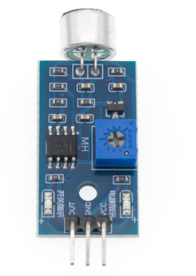
The Sound Sensor Module (Manufacturer: STMicroelectronics, Part ID: LM393) is a device designed to detect sound levels and convert them into an electrical signal. It is commonly used in projects requiring sound detection or voice activation. The module is based on the LM393 comparator and includes a microphone, signal processing circuitry, and an adjustable sensitivity potentiometer.
Explore Projects Built with Sound Sensor Module
 Open Project in Cirkit Designer
 Open Project in Cirkit Designer
 Open Project in Cirkit Designer
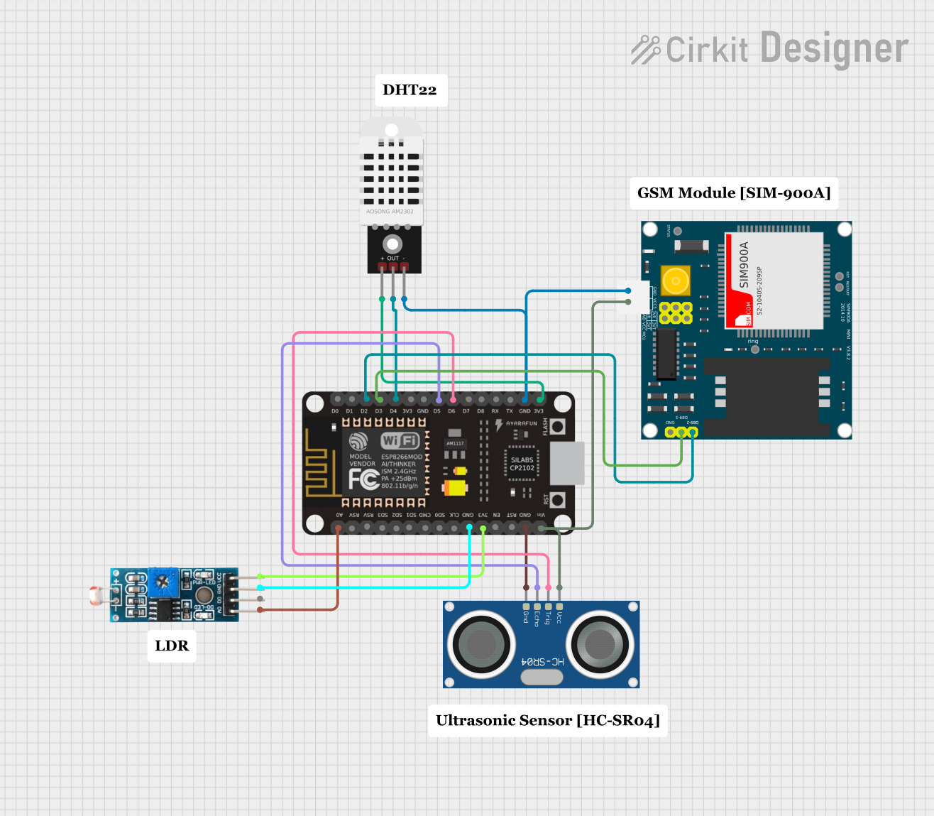 Open Project in Cirkit Designer
Explore Projects Built with Sound Sensor Module
Open Project in Cirkit DesignerOpen Project in Cirkit DesignerOpen Project in Cirkit DesignerOpen Project in Cirkit DesignerCommon Applications
- Voice-activated systems
- Sound level monitoring
- Security systems (e.g., detecting glass breaking)
- Interactive projects (e.g., clapping to trigger actions)
- Audio-based robotics
Technical Specifications
The following table outlines the key technical details of the Sound Sensor Module:
| Parameter | Value |
|---|---|
| Operating Voltage | 3.3V to 5V |
| Output Type | Digital (DO) and Analog (AO) |
| Sensitivity Adjustment | Via onboard potentiometer |
| Microphone Type | Electret Condenser Microphone |
| Comparator IC | LM393 |
| Dimensions | ~32mm x 15mm x 12mm |
| Mounting Holes | 2 x M3 holes |
Pin Configuration
The Sound Sensor Module typically has a 4-pin interface. The pin descriptions are as follows:
| Pin | Name | Description |
|---|---|---|
| 1 | VCC | Power supply input (3.3V to 5V) |
| 2 | GND | Ground connection |
| 3 | DO | Digital output (HIGH when sound exceeds threshold) |
| 4 | AO | Analog output (proportional to sound intensity) |
Usage Instructions
Connecting the Sound Sensor Module
- Power the Module: Connect the
VCCpin to a 3.3V or 5V power source and theGNDpin to ground. - Choose Output Type:
- Use the
DOpin for digital output. The output will be HIGH when the sound level exceeds the threshold set by the potentiometer. - Use the
AOpin for analog output. This provides a continuous voltage proportional to the detected sound intensity.
- Use the
- Adjust Sensitivity: Turn the onboard potentiometer clockwise to increase sensitivity or counterclockwise to decrease it.
Example Circuit with Arduino UNO
Below is an example of how to connect the Sound Sensor Module to an Arduino UNO:
| Sound Sensor Pin | Arduino UNO Pin |
|---|---|
| VCC | 5V |
| GND | GND |
| DO | Digital Pin 2 |
| AO | Analog Pin A0 |
Example Code
The following Arduino code demonstrates how to use both the digital and analog outputs of the Sound Sensor Module:
// Define pins for the sound sensor
const int digitalPin = 2; // Digital output pin from the sensor
const int analogPin = A0; // Analog output pin from the sensor

void setup() {
  pinMode(digitalPin, INPUT); // Set digital pin as input
  Serial.begin(9600);         // Initialize serial communication
}

void loop() {
  // Read digital output (HIGH or LOW)
  int digitalValue = digitalRead(digitalPin);

  // Read analog output (0-1023)
  int analogValue = analogRead(analogPin);

  // Print the values to the Serial Monitor
  Serial.print("Digital Output: ");
  Serial.print(digitalValue);
  Serial.print(" | Analog Output: ");
  Serial.println(analogValue);

  delay(500); // Wait for 500ms before the next reading
}
Best Practices
- Avoid placing the module near noisy power sources or high-frequency circuits to reduce interference.
- Use the potentiometer to fine-tune the sensitivity for your specific application.
- For long-term use, ensure the module is mounted securely to prevent damage to the microphone.
Troubleshooting and FAQs
Common Issues
No Output from the Module:
- Ensure the module is powered correctly (check
VCCandGNDconnections). - Verify that the sensitivity potentiometer is not set too low.
- Ensure the module is powered correctly (check
Digital Output Always HIGH or LOW:
- Adjust the sensitivity potentiometer to ensure the threshold matches the sound level.
- Check for excessive background noise that might trigger the sensor.
Analog Output Not Changing:
- Confirm that the microphone is functional and not physically damaged.
- Ensure the
AOpin is connected to an analog input on the microcontroller.
FAQs
Q: Can the module detect specific sounds (e.g., voice or clapping)?
A: The module detects sound intensity but cannot differentiate between specific sounds. Additional signal processing is required for sound classification.
Q: Can I use the module with a 3.3V microcontroller?
A: Yes, the module operates at 3.3V to 5V, making it compatible with 3.3V microcontrollers like ESP32 or Raspberry Pi Pico.
Q: How do I increase the detection range?
A: Increase the sensitivity using the potentiometer. However, note that higher sensitivity may also increase false triggers from background noise.
Q: Is the module suitable for outdoor use?
A: The module is not weatherproof. For outdoor use, ensure it is housed in a protective enclosure.