How to Use LTC 3780 AUTO DC BUCK BOOST: Examples, Pinouts, and Specs
Introduction
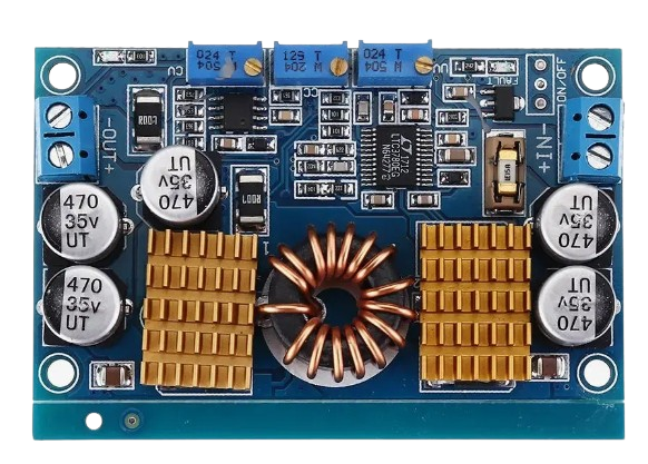
The LTC 3780 is a high-efficiency DC-DC converter capable of operating as both a buck (step-down) and boost (step-up) regulator. It is designed to provide a stable output voltage from a varying input voltage, making it ideal for applications where the input voltage can fluctuate above or below the desired output voltage. This versatility makes the LTC 3780 a popular choice for battery-powered systems, energy harvesting applications, and automotive electronics.
Explore Projects Built with LTC 3780 AUTO DC BUCK BOOST


Explore Projects Built with LTC 3780 AUTO DC BUCK BOOST
Common Applications and Use Cases
- Battery-powered devices (e.g., laptops, portable electronics)
- Solar energy systems and energy harvesting
- Automotive electronics (e.g., voltage stabilization in vehicles)
- Industrial power supplies
- LED drivers and lighting systems
Technical Specifications
The LTC 3780 offers a wide range of features and capabilities. Below are its key technical specifications:
| Parameter | Value |
|---|---|
| Input Voltage Range | 4V to 38V |
| Output Voltage Range | 0.8V to 30V |
| Output Current | Up to 10A (depending on external components) |
| Efficiency | Up to 98% |
| Switching Frequency | Adjustable, 200kHz to 400kHz |
| Operating Temperature Range | -40°C to 125°C |
| Control Mode | Current-mode control |
Pin Configuration and Descriptions
The LTC 3780 is typically available in a 16-pin package. Below is the pin configuration and description:
| Pin Number | Pin Name | Description |
|---|---|---|
| 1 | VIN | Input voltage pin. Connect to the input power source. |
| 2 | VOUT | Output voltage pin. Connect to the load. |
| 3 | FB | Feedback pin. Used to set the output voltage via a resistor divider. |
| 4 | ITH | Compensation pin. Connect to a capacitor and resistor for loop compensation. |
| 5 | SGND | Signal ground. Connect to the system ground. |
| 6 | RT | Timing resistor pin. Sets the switching frequency. |
| 7 | SYNC | Synchronization pin. Allows synchronization to an external clock. |
| 8 | RUN | Enable pin. Pull high to enable the converter. |
| 9 | SS | Soft-start pin. Connect a capacitor to control startup behavior. |
| 10 | PGND | Power ground. Connect to the system ground. |
| 11 | SW | Switch node. Connect to the inductor and diode. |
| 12 | BOOST | Boost pin. Connect to a capacitor and diode for high-side drive. |
| 13 | INTVCC | Internal regulator output. Connect a capacitor for stability. |
| 14 | TG | Top gate drive pin. Drives the high-side MOSFET. |
| 15 | BG | Bottom gate drive pin. Drives the low-side MOSFET. |
| 16 | EXTVCC | External VCC input. Can be used to bypass the internal regulator. |
Usage Instructions
How to Use the LTC 3780 in a Circuit
- Input and Output Connections: Connect the input voltage source to the VIN pin and the load to the VOUT pin. Ensure the input voltage is within the specified range (4V to 38V).
- Feedback Resistor Divider: Use a resistor divider network connected to the FB pin to set the desired output voltage. The formula for the output voltage is: [ V_{OUT} = V_{REF} \times \left(1 + \frac{R1}{R2}\right) ] where ( V_{REF} ) is typically 0.8V.
- Inductor and Capacitor Selection: Choose an inductor and capacitors with appropriate ratings for your desired output current and voltage ripple.
- Soft-Start Configuration: Connect a capacitor to the SS pin to control the startup time and reduce inrush current.
- Switching Frequency: Set the switching frequency by connecting a resistor to the RT pin. Refer to the datasheet for the resistor value corresponding to your desired frequency.
- Enable the Converter: Pull the RUN pin high to enable the LTC 3780. This can be done using a microcontroller or a simple pull-up resistor.
Important Considerations and Best Practices
- Thermal Management: Ensure proper heat dissipation by using a heatsink or placing the component on a PCB with good thermal conductivity.
- Input and Output Capacitors: Use low-ESR capacitors to minimize voltage ripple and improve stability.
- Inductor Selection: Choose an inductor with a current rating higher than the maximum output current to avoid saturation.
- PCB Layout: Minimize the length of high-current paths and place decoupling capacitors close to the VIN and VOUT pins.
Example: Using the LTC 3780 with an Arduino UNO
The LTC 3780 can be controlled using an Arduino UNO to enable or disable the converter and monitor the output voltage. Below is an example code snippet:
// Define the RUN pin connected to the Arduino
const int runPin = 7; // Connect RUN pin of LTC 3780 to Arduino digital pin 7

// Define the analog input pin for voltage monitoring
const int voltagePin = A0; // Connect FB pin to Arduino analog pin A0 via a resistor divider

void setup() {
  // Initialize the RUN pin as an output
  pinMode(runPin, OUTPUT);

  // Enable the LTC 3780 by setting the RUN pin high
  digitalWrite(runPin, HIGH);

  // Initialize serial communication for monitoring
  Serial.begin(9600);
}

void loop() {
  // Read the output voltage (scaled by the resistor divider)
  int rawValue = analogRead(voltagePin);

  // Convert the raw ADC value to voltage (adjust the scale factor as needed)
  float outputVoltage = (rawValue / 1023.0) * 5.0 * (R1 + R2) / R2;

  // Print the output voltage to the serial monitor
  Serial.print("Output Voltage: ");
  Serial.print(outputVoltage);
  Serial.println(" V");

  delay(1000); // Wait for 1 second before the next reading
}
Note: Replace
R1andR2in the code with the actual resistor values used in your feedback network.
Troubleshooting and FAQs
Common Issues and Solutions
No Output Voltage:
- Ensure the RUN pin is pulled high to enable the converter.
- Check the input voltage and ensure it is within the specified range.
- Verify the feedback resistor network and ensure it is configured correctly.
Excessive Output Ripple:
- Use low-ESR capacitors at the input and output.
- Check the inductor value and ensure it is appropriate for the load current.
Overheating:
- Ensure proper thermal management with heatsinks or a well-designed PCB.
- Verify that the input and output currents are within the specified limits.
Unstable Output Voltage:
- Check the compensation network connected to the ITH pin.
- Ensure the switching frequency is set correctly using the RT pin.
FAQs
Q: Can the LTC 3780 handle negative input voltages?
A: No, the LTC 3780 is designed for positive input voltages only. Applying a negative voltage may damage the component.
Q: How do I synchronize the LTC 3780 with an external clock?
A: Connect the external clock signal to the SYNC pin. Ensure the clock frequency is within the supported range (200kHz to 400kHz).
Q: What is the maximum output current the LTC 3780 can provide?
A: The maximum output current depends on the external components (e.g., MOSFETs, inductor) and thermal management. With proper design, it can deliver up to 10A.
Q: Can I use the LTC 3780 for charging batteries?
A: Yes, the LTC 3780 can be used for battery charging applications, but additional circuitry may be required to implement proper charging profiles.