How to Use L298: Examples, Pinouts, and Specs

Introduction
The L298 is a high-power dual H-bridge motor driver integrated circuit (IC) designed to control the speed and direction of DC motors and stepper motors. It is capable of driving two DC motors simultaneously in either direction or one stepper motor in both bipolar and unipolar configurations. The L298 is widely used in robotics, CNC machines, and other applications where precise motor control is required.
Explore Projects Built with L298
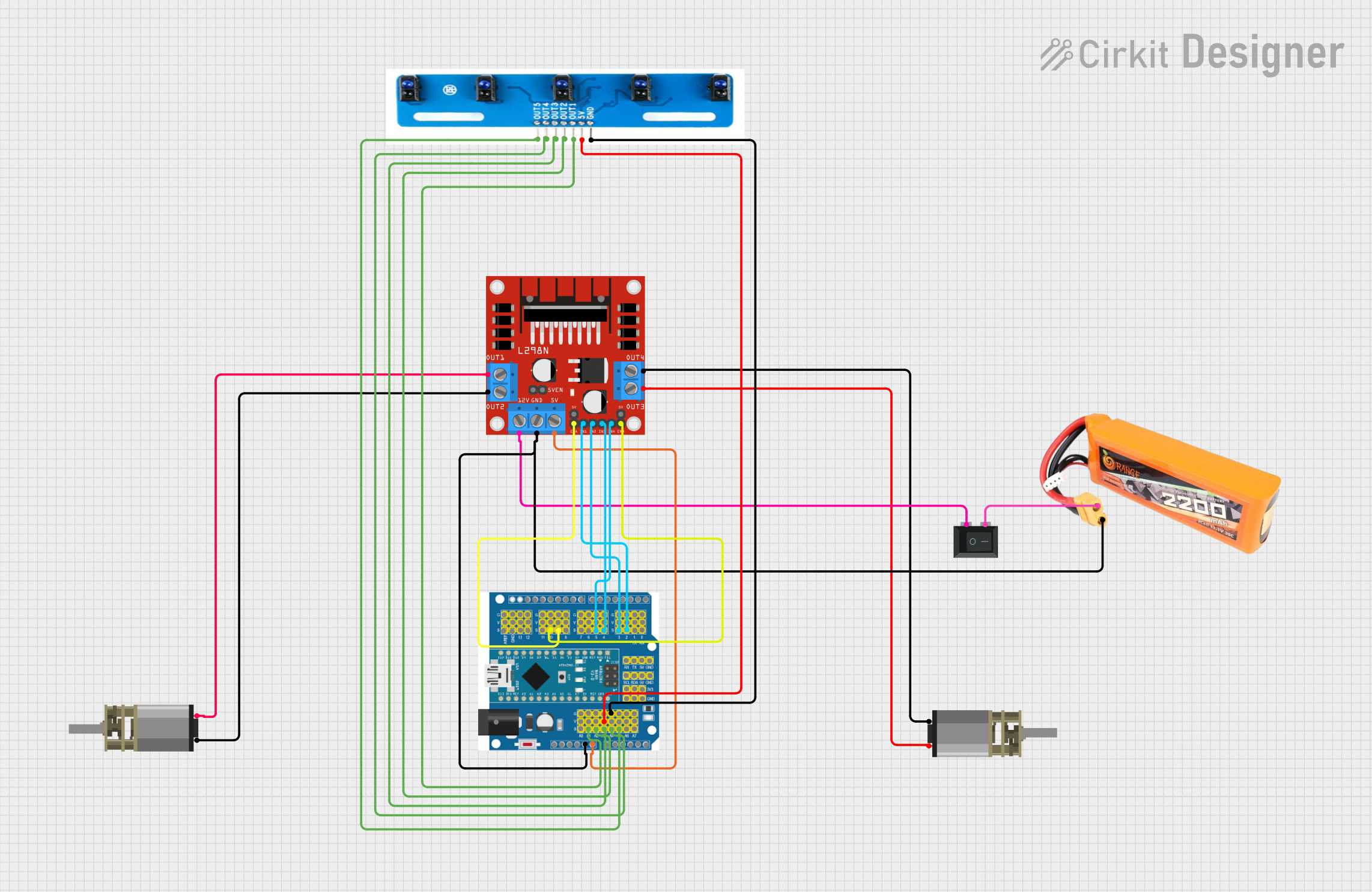

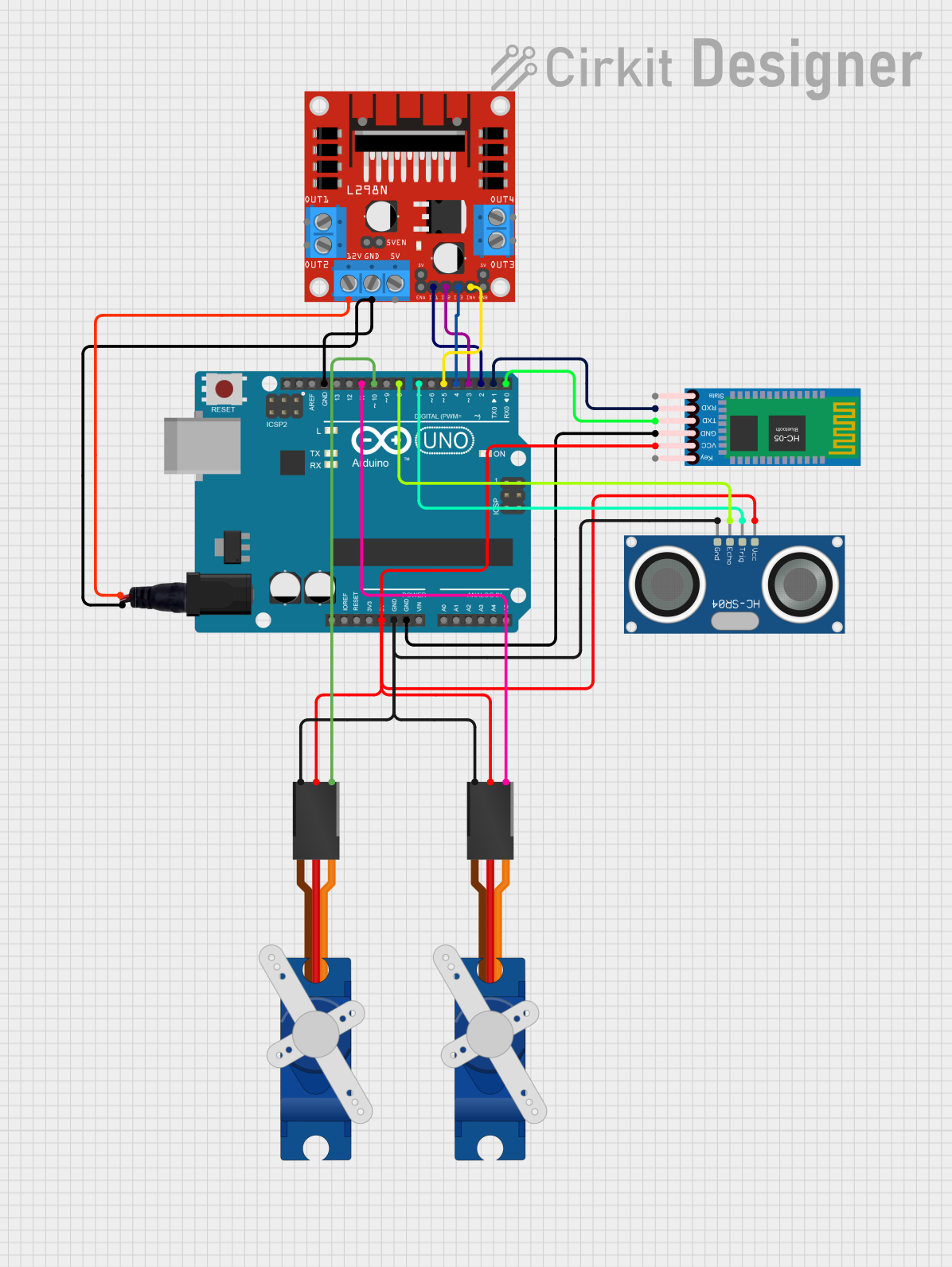
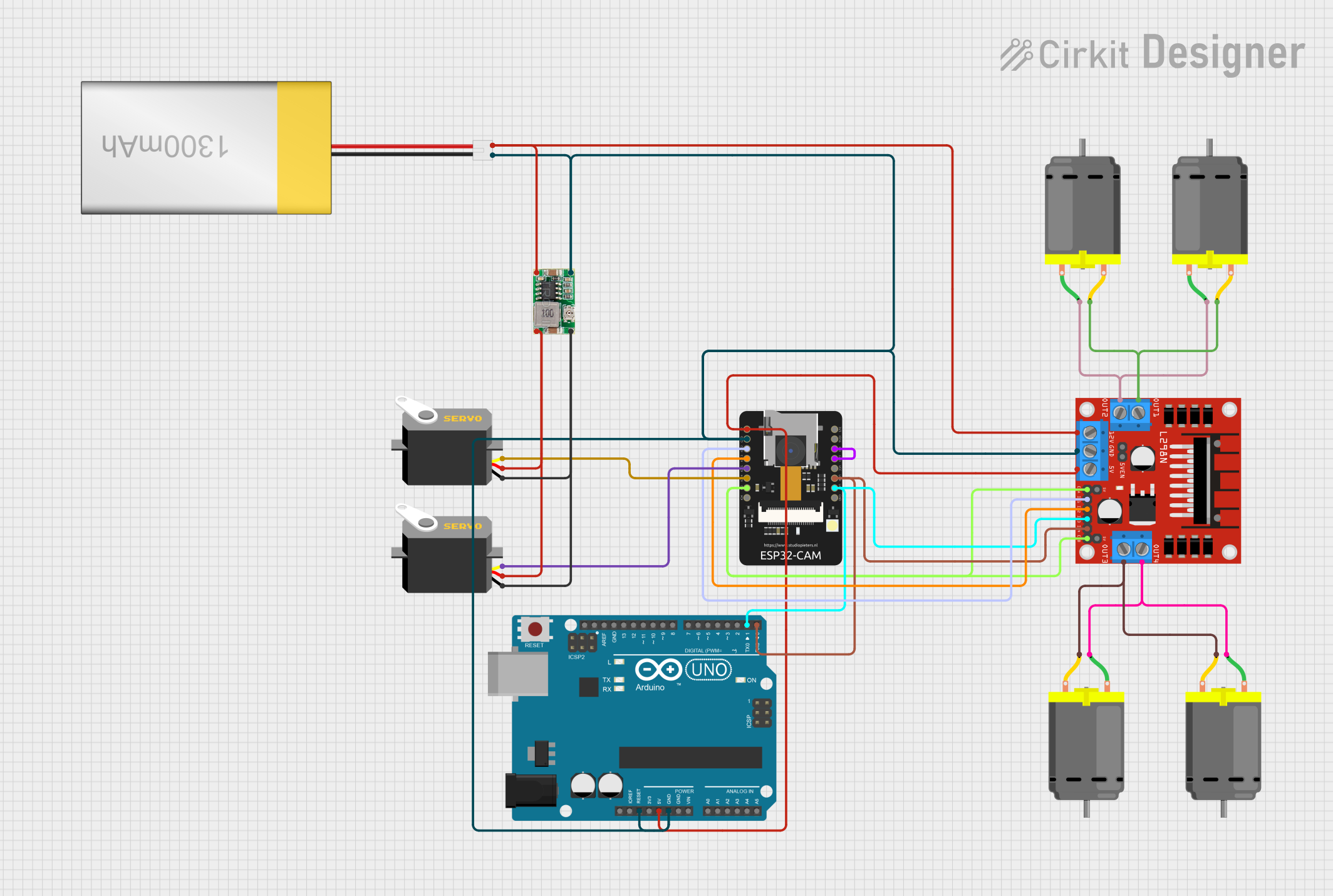
Explore Projects Built with L298
Common Applications and Use Cases
- Robotics: Driving wheels or tracks
- CNC machines: Controlling stepper motors for precise movements
- Home automation: Operating blinds, curtains, or other motorized fixtures
- Hobby projects: Remote-controlled vehicles, drones, etc.
Technical Specifications
Key Technical Details
- Operating Voltage (V_S): Up to 46V
- Logic Voltage (V_SS): 4.5V to 7V
- Peak Output Current (I_O): 2A per channel
- Total Power Dissipation (T_PD): 25W (at T_C = 75°C)
Pin Configuration and Descriptions
| Pin Number | Pin Name | Description |
|---|---|---|
| 1 | Vs | Supply voltage for the H-bridge output stages (Power input) |
| 2 | GND | Ground |
| 3 | Vss | Supply voltage for the logic circuitry (Logic power input) |
| 4 | Out 1 | Output to motor channel A (Output 1) |
| 5 | Out 2 | Output to motor channel A (Output 2) |
| 6 | Vs | Sense voltage for channel A (Current sensing) |
| 7 | In 1 | Input 1 for channel A (Logic input) |
| 8 | In 2 | Input 2 for channel A (Logic input) |
| ... | ... | ... |
| 15 | In 3 | Input 1 for channel B (Logic input) |
| 16 | In 4 | Input 2 for channel B (Logic input) |
| 17 | Sense B | Sense voltage for channel B (Current sensing) |
| 18 | Out 3 | Output to motor channel B (Output 3) |
| 19 | Out 4 | Output to motor channel B (Output 4) |
| 20 | GND | Ground |
Usage Instructions
How to Use the Component in a Circuit
- Connect the motor supply voltage (up to 46V) to pin 1 (Vs).
- Connect the ground of the power supply to pin 2 (GND).
- Apply the logic supply voltage (4.5V to 7V) to pin 3 (Vss).
- Connect the outputs (Out 1, Out 2, Out 3, Out 4) to the motors.
- Use the input pins (In 1, In 2, In 3, In 4) to control the motor direction and speed.
- Optionally, connect a sense resistor to pins 6 (Vs) and 17 (Sense B) for current sensing.
Important Considerations and Best Practices
- Ensure that the power supply can handle the current requirements of the motors.
- Use appropriate heat sinking for the L298 IC to prevent thermal shutdown or damage.
- Implement flyback diodes across the motor terminals to protect the L298 from voltage spikes.
- Avoid running the IC at its maximum ratings for extended periods to ensure reliability.
Example Code for Arduino UNO
// Define the L298N control pins
#define IN1 2
#define IN2 3
#define IN3 4
#define IN4 5

void setup() {
  // Set all the control pins as outputs
  pinMode(IN1, OUTPUT);
  pinMode(IN2, OUTPUT);
  pinMode(IN3, OUTPUT);
  pinMode(IN4, OUTPUT);
}

void loop() {
  // Spin motor A clockwise
  digitalWrite(IN1, HIGH);
  digitalWrite(IN2, LOW);
  // Spin motor B counterclockwise
  digitalWrite(IN3, LOW);
  digitalWrite(IN4, HIGH);
  delay(2000); // Run motors for 2 seconds

  // Stop both motors
  digitalWrite(IN1, LOW);
  digitalWrite(IN2, LOW);
  digitalWrite(IN3, LOW);
  digitalWrite(IN4, LOW);
  delay(1000); // Wait for 1 second

  // Add more control logic as needed for your application
}
Troubleshooting and FAQs
Common Issues Users Might Face
- Motor not running: Check power supply connections, ensure that the logic inputs are correctly set, and verify that the motor is functional.
- Overheating: Ensure proper heat sinking and current limits are not exceeded.
- Inconsistent motor behavior: Check for loose connections and ensure that the input signals are clean and without noise.
Solutions and Tips for Troubleshooting
- Use a multimeter to check for proper voltage levels at the power and logic inputs.
- If using PWM to control motor speed, ensure that the frequency is within the IC's operating range.
- Double-check the wiring against the pin configuration table to ensure all connections are correct.
FAQs
Q: Can the L298 drive two motors independently? A: Yes, the L298 can control two DC motors independently with separate input controls for each channel.
Q: What is the maximum current the L298 can handle? A: The L298 can handle peak currents of up to 2A per channel.
Q: Do I need to use current sensing? A: Current sensing is optional but recommended if you need to monitor or limit the current to the motors.
Q: Can I use the L298 to drive a bipolar stepper motor? A: Yes, the L298 can be used to drive a bipolar stepper motor by appropriately energizing the coils in sequence.