How to Use WeAct ESP32H2-N4: Examples, Pinouts, and Specs
Introduction
The WeAct ESP32H2-N4 is a compact and versatile development board built around the ESP32-H2 chip. This board integrates Wi-Fi and Bluetooth Low Energy (BLE) capabilities, making it an excellent choice for IoT (Internet of Things) applications. It is designed to deliver low power consumption, high performance, and flexibility for developers working on smart devices, home automation, wearables, and other connected systems.
Explore Projects Built with WeAct ESP32H2-N4


Explore Projects Built with WeAct ESP32H2-N4
Common Applications and Use Cases
- IoT Devices: Smart home systems, environmental monitoring, and connected appliances.
- Wearables: Fitness trackers, health monitoring devices, and smart accessories.
- Industrial Automation: Wireless sensor networks and machine-to-machine communication.
- Prototyping: Rapid development of wireless communication systems.
- Educational Projects: Learning and experimenting with Wi-Fi and BLE technologies.
Technical Specifications
Key Technical Details
| Parameter | Value |
|---|---|
| Chipset | ESP32-H2 |
| Wireless Connectivity | Wi-Fi (802.11 b/g/n) and Bluetooth Low Energy (BLE 5.0) |
| Operating Voltage | 3.3V |
| Flash Memory | 4MB (integrated) |
| SRAM | 320KB |
| GPIO Pins | 26 (configurable for digital I/O, ADC, PWM, I2C, SPI, UART, etc.) |
| ADC Resolution | 12-bit |
| Operating Temperature | -40°C to +85°C |
| Power Consumption | Ultra-low power consumption in deep sleep mode (<10 µA) |
| Dimensions | 18mm x 25mm |
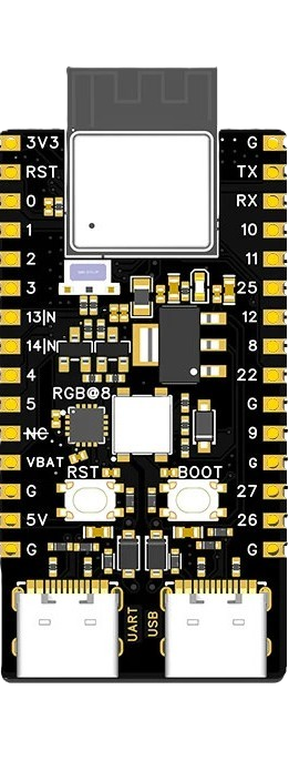
Pin Configuration and Descriptions
The WeAct ESP32H2-N4 features a total of 26 GPIO pins, which can be configured for various functions. Below is the pinout description:
| Pin Number | Pin Name | Function | Description |
|---|---|---|---|
| 1 | GND | Ground | Common ground for the board |
| 2 | 3V3 | Power Supply | 3.3V power input/output |
| 3 | GPIO0 | Digital I/O, Boot Mode Selection | Configurable GPIO, used for boot mode |
| 4 | GPIO1 | Digital I/O, UART TX | Configurable GPIO, UART transmit |
| 5 | GPIO2 | Digital I/O, UART RX | Configurable GPIO, UART receive |
| 6 | GPIO3 | Digital I/O, ADC, PWM | Configurable GPIO, analog input, or PWM |
| 7 | GPIO4 | Digital I/O, I2C SDA | Configurable GPIO, I2C data line |
| 8 | GPIO5 | Digital I/O, I2C SCL | Configurable GPIO, I2C clock line |
| 9 | GPIO6 | Digital I/O, SPI MOSI | Configurable GPIO, SPI data out |
| 10 | GPIO7 | Digital I/O, SPI MISO | Configurable GPIO, SPI data in |
| 11 | GPIO8 | Digital I/O, SPI SCK | Configurable GPIO, SPI clock |
| 12 | GPIO9 | Digital I/O, SPI CS | Configurable GPIO, SPI chip select |
| ... | ... | ... | ... |
Note: Refer to the official datasheet for the complete pinout and advanced configurations.
Usage Instructions
How to Use the Component in a Circuit
Powering the Board:
- Supply 3.3V to the
3V3pin and connect theGNDpin to the ground of your circuit. - Alternatively, you can power the board via the USB interface (if available on your specific model).
- Supply 3.3V to the
Programming the Board:
- Use the Arduino IDE, PlatformIO, or ESP-IDF to program the ESP32H2-N4.
- Connect the board to your computer via USB or a UART-to-USB adapter.
- Select the appropriate board and port in your development environment.
Connecting Peripherals:
- Use the GPIO pins to interface with sensors, actuators, and other devices.
- Configure the pins in your code for the desired functionality (e.g., digital I/O, ADC, PWM).
Wireless Communication:
- Use the built-in Wi-Fi and BLE capabilities to connect to networks or communicate with other devices.
Important Considerations and Best Practices
- Voltage Levels: Ensure all connected peripherals operate at 3.3V logic levels to avoid damaging the board.
- Deep Sleep Mode: Utilize the deep sleep mode for battery-powered applications to minimize power consumption.
- Pin Multiplexing: Be aware that some pins have multiple functions. Check the datasheet to avoid conflicts.
- Antenna Placement: Ensure the onboard antenna has sufficient clearance from metal objects to maintain optimal wireless performance.
Example Code for Arduino UNO Integration
Below is an example of using the WeAct ESP32H2-N4 to read a temperature sensor and send the data over Wi-Fi:
#include <WiFi.h> // Include the Wi-Fi library

// Wi-Fi credentials
const char* ssid = "Your_SSID";
const char* password = "Your_PASSWORD";

void setup() {
  Serial.begin(115200); // Initialize serial communication
  WiFi.begin(ssid, password); // Connect to Wi-Fi

  // Wait for connection
  while (WiFi.status() != WL_CONNECTED) {
    delay(1000);
    Serial.println("Connecting to Wi-Fi...");
  }
  Serial.println("Connected to Wi-Fi!");
}

void loop() {
  // Example: Read temperature sensor data (replace with actual sensor code)
  int temperature = analogRead(34); // Read from GPIO34 (ADC pin)
  Serial.print("Temperature: ");
  Serial.println(temperature);

  delay(2000); // Wait 2 seconds before the next reading
}
Note: Replace
Your_SSIDandYour_PASSWORDwith your Wi-Fi network credentials.
Troubleshooting and FAQs
Common Issues and Solutions
Board Not Detected by Computer:
- Ensure the USB cable is functional and supports data transfer.
- Install the necessary USB-to-UART drivers for your operating system.
Wi-Fi Connection Fails:
- Double-check the SSID and password in your code.
- Ensure the Wi-Fi network is within range and operational.
GPIO Pin Not Responding:
- Verify the pin configuration in your code.
- Check for potential conflicts with other peripherals using the same pin.
High Power Consumption:
- Ensure the board is in deep sleep mode when not actively processing.
- Disconnect unused peripherals to reduce power draw.
FAQs
Q: Can I power the board with 5V?
- A: No, the board operates at 3.3V. Supplying 5V directly to the pins may damage the board.
Q: Does the board support OTA (Over-the-Air) updates?
- A: Yes, the ESP32-H2 chip supports OTA updates. Refer to the ESP-IDF documentation for implementation details.
Q: How do I reset the board?
- A: Press the onboard reset button (if available) or toggle the power supply.
Q: Can I use the board with batteries?
- A: Yes, the board is suitable for battery-powered applications. Use a 3.3V regulator if necessary.
This concludes the documentation for the WeAct ESP32H2-N4. For further details, refer to the official datasheet and resources provided by WeAct.