How to Use Micro USB to Cable (2 Pin): Examples, Pinouts, and Specs
Introduction
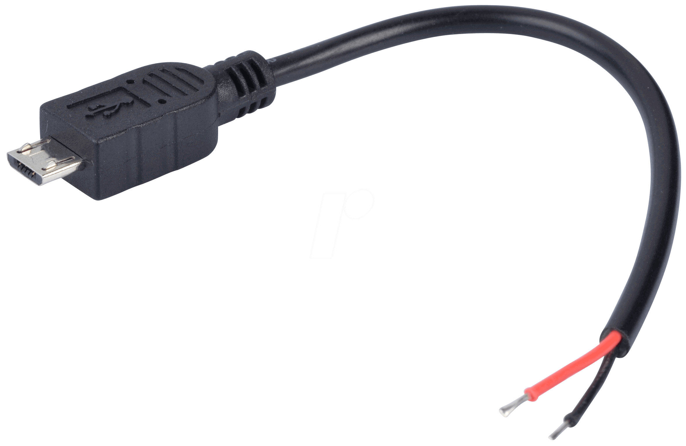
The Micro USB to Cable (2 Pin) is a versatile electronic component designed to connect devices with a Micro USB port to a power source or data transfer interface. This cable features two pins, typically used for power delivery and data transmission. It is widely used in applications such as charging mobile devices, powering small electronics, and enabling data communication between devices.
Explore Projects Built with Micro USB to Cable (2 Pin)


Explore Projects Built with Micro USB to Cable (2 Pin)
Common Applications and Use Cases
- Charging smartphones, tablets, and other portable devices.
- Powering small electronic projects, such as Arduino-based systems.
- Facilitating data transfer between devices, such as computers and peripherals.
- Providing a compact and reliable connection for embedded systems.
Technical Specifications
Below are the key technical details for the Micro USB to Cable (2 Pin):
| Parameter | Specification |
|---|---|
| Manufacturer | Unknown |
| Manufacturer Part ID | USB |
| Connector Type | Micro USB (Type B) |
| Number of Pins | 2 |
| Voltage Rating | 5V DC (typical) |
| Current Rating | Up to 2A (depending on cable quality) |
| Cable Length | Varies (commonly 0.5m to 2m) |
| Data Transfer Speed | Up to 480 Mbps (USB 2.0 standard) |
| Operating Temperature | -20°C to 60°C |
Pin Configuration and Descriptions
The Micro USB to Cable (2 Pin) uses two primary pins for its operation:
| Pin Number | Name | Description |
|---|---|---|
| 1 | VBUS | Power supply pin (5V DC) |
| 2 | D+ / D- | Data transmission pin (used for data or signaling) |
Note: The cable may internally include additional pins for shielding or ground, but only two pins are actively used for power and data in this configuration.
Usage Instructions
How to Use the Component in a Circuit
Powering a Device:
- Connect the Micro USB end of the cable to the device's Micro USB port.
- Attach the other end of the cable to a 5V power source, such as a USB wall adapter or a power bank.
- Ensure the power source provides sufficient current (up to 2A) for the connected device.
Data Transfer:
- Connect the Micro USB end to the device requiring data communication.
- Plug the other end into a computer or compatible host device.
- Ensure the host device supports USB 2.0 or higher for optimal data transfer speeds.
Important Considerations and Best Practices
- Cable Quality: Use a high-quality cable to ensure reliable power delivery and data transfer.
- Current Rating: Verify that the power source can supply the required current for your device.
- Avoid Overheating: Do not exceed the cable's voltage or current rating to prevent overheating or damage.
- Secure Connections: Ensure the Micro USB connector is firmly seated in the port to avoid intermittent connections.
Example: Using with an Arduino UNO
The Micro USB to Cable (2 Pin) can be used to power an Arduino UNO via a USB power source. Below is an example of how to use the cable for powering the Arduino:
- Connect the Micro USB end of the cable to a USB power adapter.
- Plug the adapter into a wall socket or power bank.
- Insert the other end of the cable into the Arduino UNO's USB port.
If you are using the cable for data transfer (e.g., uploading code to the Arduino UNO), connect the cable to a computer instead of a power adapter.
Sample Arduino Code
Here is a simple Arduino sketch to test the connection:
// Blink an LED connected to pin 13 on the Arduino UNO
// Ensure the Arduino is powered via the Micro USB to Cable (2 Pin)

// The setup function runs once when the Arduino is powered on
void setup() {
  pinMode(13, OUTPUT); // Set pin 13 as an output pin
}

// The loop function runs repeatedly
void loop() {
  digitalWrite(13, HIGH); // Turn the LED on
  delay(1000);            // Wait for 1 second
  digitalWrite(13, LOW);  // Turn the LED off
  delay(1000);            // Wait for 1 second
}
Note: Ensure the Arduino IDE is installed on your computer for uploading the code.
Troubleshooting and FAQs
Common Issues Users Might Face
Device Not Charging:
- Cause: The power source may not provide sufficient current.
- Solution: Use a power source with a higher current rating (e.g., 2A).
Intermittent Connection:
- Cause: Loose or damaged connectors.
- Solution: Ensure the Micro USB connector is securely plugged in. Replace the cable if necessary.
Data Transfer Fails:
- Cause: The cable may not support data transfer.
- Solution: Use a cable specifically designed for both power and data.
Overheating:
- Cause: Exceeding the cable's voltage or current rating.
- Solution: Verify the power source's output and ensure it is within the cable's specifications.
Solutions and Tips for Troubleshooting
- Inspect the Cable: Check for visible damage, such as frayed wires or bent connectors.
- Test with Another Device: Use the cable with a different device to determine if the issue is with the cable or the device.
- Use a Multimeter: Measure the voltage and current to ensure the cable is delivering the correct power.
By following these guidelines, you can effectively use the Micro USB to Cable (2 Pin) for a variety of applications while avoiding common pitfalls.