
How to Use Power Supply: Examples, Pinouts, and Specs
 Design with Power Supply in Cirkit Designer
Introduction
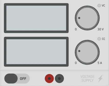
A power supply is a critical electronic component that provides electrical energy to a circuit. It converts AC (alternating current) or DC (direct current) voltage from a source into a stable and usable form for powering electronic components. Power supplies are available in various types, including linear, switching, and unregulated, each suited for specific applications.
Common applications of power supplies include:
- Powering microcontrollers, sensors, and actuators in embedded systems
- Providing stable voltage for laboratory testing and prototyping
- Supplying energy to consumer electronics, such as laptops and smartphones
- Driving industrial equipment and automation systems
Explore Projects Built with Power Supply
 Open Project in Cirkit Designer
 Open Project in Cirkit Designer
 Open Project in Cirkit Designer
 Open Project in Cirkit Designer
Explore Projects Built with Power Supply
Open Project in Cirkit DesignerOpen Project in Cirkit DesignerOpen Project in Cirkit DesignerOpen Project in Cirkit DesignerTechnical Specifications
Below are the general technical specifications for a typical power supply. Specifications may vary depending on the type and model.
General Specifications
- Input Voltage Range: 100-240V AC (for AC-DC power supplies) or 5-48V DC (for DC-DC converters)
- Output Voltage Range: 1.2V to 48V DC (depending on the model)
- Output Current: 0.1A to 50A (depending on the power supply rating)
- Power Rating: 1W to 1000W
- Efficiency: 70% to 95% (higher for switching power supplies)
- Ripple and Noise: <50mV (for regulated power supplies)
- Protection Features: Overvoltage, overcurrent, short-circuit, and thermal protection
Pin Configuration and Descriptions
The pin configuration of a power supply depends on its type. Below is an example of a DC-DC power supply module with a standard pinout.
| Pin Name | Description |
|---|---|
| VIN | Input voltage pin. Connects to the DC input source (e.g., battery or adapter). |
| GND | Ground pin. Connects to the ground of the circuit. |
| VOUT | Output voltage pin. Provides the regulated DC output voltage. |
| ADJ (optional) | Adjustment pin. Used to fine-tune the output voltage (if supported). |
For AC-DC power supplies, the input and output terminals are typically labeled as:
- L (Line): AC live input
- N (Neutral): AC neutral input
- +V: Positive DC output
- -V: Negative DC output (ground)
Usage Instructions
How to Use the Power Supply in a Circuit
Determine the Voltage and Current Requirements:
- Identify the voltage and current requirements of your circuit or device.
- Ensure the power supply's output voltage and current ratings match or exceed these requirements.
Connect the Input:
- For AC-DC power supplies, connect the AC input terminals (L and N) to the mains power source.
- For DC-DC power supplies, connect the VIN and GND pins to the DC input source.
Connect the Output:
- Connect the VOUT and GND pins (or +V and -V terminals) to the load or circuit.
Adjust the Output Voltage (if applicable):
- If the power supply has an adjustment pin or potentiometer, use it to fine-tune the output voltage.
Power On:
- Turn on the power supply and verify the output voltage using a multimeter before connecting sensitive components.
Important Considerations and Best Practices
- Always verify the input and output voltage ratings before connecting the power supply to avoid damage.
- Use appropriate fuses or circuit breakers for added protection.
- Ensure proper ventilation and cooling for high-power supplies to prevent overheating.
- Avoid overloading the power supply beyond its rated current capacity.
- For sensitive circuits, use a regulated power supply to minimize ripple and noise.
Example: Using a Power Supply with an Arduino UNO
To power an Arduino UNO using a DC-DC power supply:
- Set the power supply's output voltage to 5V or 9V (depending on the Arduino's input requirements).
- Connect the VOUT pin of the power supply to the Arduino's VIN pin.
- Connect the GND pin of the power supply to the Arduino's GND pin.
Here is an example Arduino sketch to blink an LED while powered by the external power supply:
// Blink an LED connected to pin 13
// Ensure the Arduino is powered by the external power supply

void setup() {
  pinMode(13, OUTPUT); // Set pin 13 as an output
}

void loop() {
  digitalWrite(13, HIGH); // Turn the LED on
  delay(1000);            // Wait for 1 second
  digitalWrite(13, LOW);  // Turn the LED off
  delay(1000);            // Wait for 1 second
}
Troubleshooting and FAQs
Common Issues and Solutions
No Output Voltage:
- Check the input connections and ensure the power supply is receiving power.
- Verify that the input voltage is within the specified range.
- Inspect for blown fuses or tripped circuit breakers.
Output Voltage Too Low or Unstable:
- Ensure the load does not exceed the power supply's current rating.
- Check for loose or faulty connections.
- If using an adjustable power supply, verify the adjustment settings.
Overheating:
- Ensure proper ventilation and cooling for the power supply.
- Reduce the load if it exceeds the power supply's capacity.
Excessive Ripple or Noise:
- Use a regulated power supply for sensitive circuits.
- Add capacitors or filters to the output to reduce noise.
FAQs
Q: Can I use a power supply with a higher current rating than my device requires?
A: Yes, a power supply with a higher current rating is safe to use. The device will only draw the current it needs.
Q: What happens if I reverse the input or output connections?
A: Reversing connections can damage the power supply or the connected device. Always double-check the polarity before powering on.
Q: How do I know if my power supply is regulated?
A: Regulated power supplies maintain a constant output voltage regardless of load variations. Check the specifications or test the output under different loads to confirm.
Q: Can I use a single power supply to power multiple devices?
A: Yes, as long as the total current draw of all devices does not exceed the power supply's current rating. Use proper wiring to distribute the power.
By following these guidelines and best practices, you can ensure safe and efficient operation of your power supply in various applications.