How to Use AD5933 Dev Board: Examples, Pinouts, and Specs
Introduction
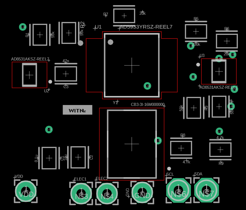
The AD5933 Dev Board, manufactured by WitNe, is a development platform built around the AD5933 integrated circuit. The AD5933 is a high-precision impedance converter that simplifies the process of measuring and analyzing impedance across a wide frequency range. This development board is designed to help users evaluate and prototype applications involving impedance spectroscopy, such as material characterization, bio-impedance analysis, and sensor development.
Explore Projects Built with AD5933 Dev Board


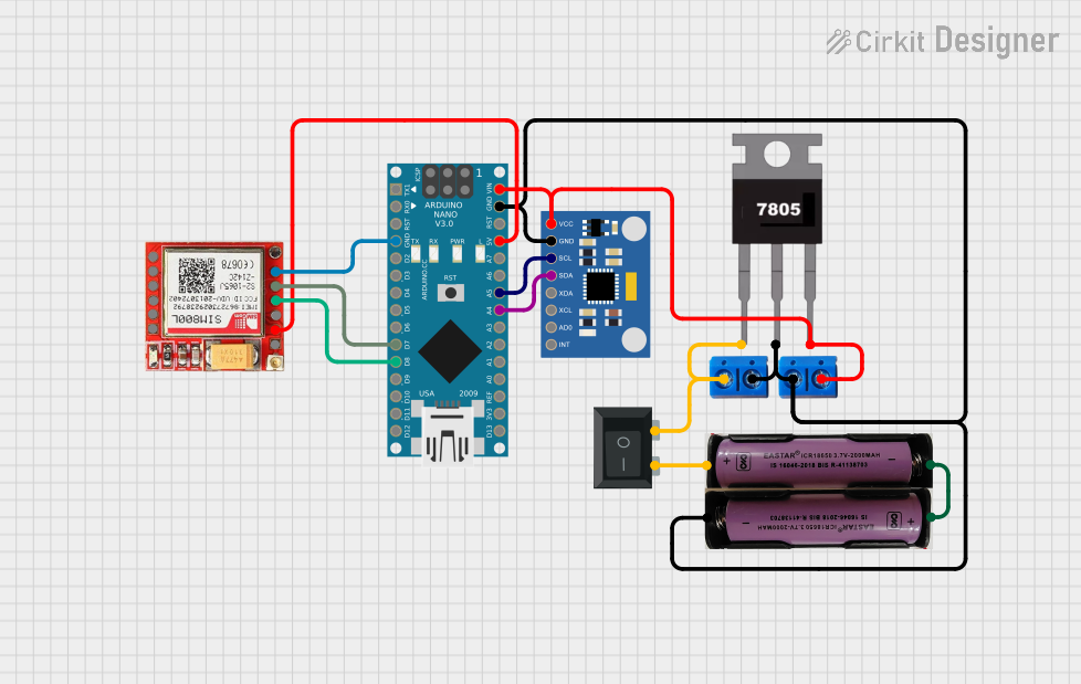
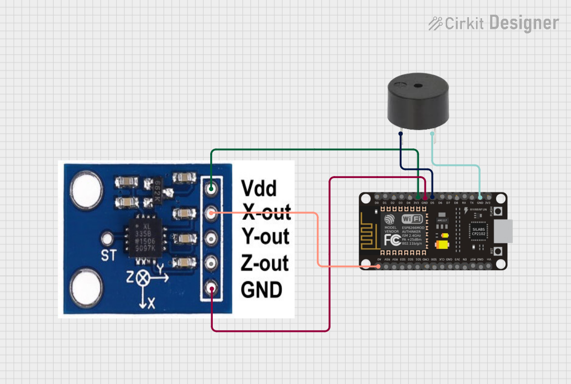
Explore Projects Built with AD5933 Dev Board
Common Applications and Use Cases
- Bio-impedance analysis for medical devices
- Material property characterization
- Corrosion monitoring in industrial systems
- Liquid and gas sensor development
- Dielectric spectroscopy
- Research and development in impedance-based systems
Technical Specifications
Key Technical Details
- Integrated Circuit: AD5933 (Impedance Converter with Programmable Frequency Generator)
- Frequency Range: 1 kHz to 100 kHz (programmable)
- Impedance Measurement Range: 1 kΩ to 10 MΩ (depending on external components)
- Power Supply Voltage: 3.3V or 5V (selectable via jumper)
- Communication Interface: I²C (Inter-Integrated Circuit)
- Onboard Oscillator: 16 MHz crystal oscillator
- PCB Dimensions: 50 mm x 50 mm
- Operating Temperature: -40°C to +85°C
Pin Configuration and Descriptions
The AD5933 Dev Board features a set of pins for power, communication, and signal connections. Below is the pinout description:
| Pin Name | Type | Description |
|---|---|---|
| VCC | Power Input | Power supply input (3.3V or 5V, depending on jumper configuration). |
| GND | Power Ground | Ground connection. |
| SDA | I²C Data Line | Serial data line for I²C communication. |
| SCL | I²C Clock Line | Serial clock line for I²C communication. |
| VIN | Analog Input | Input for the signal to be measured (connect to the impedance network). |
| VOUT | Analog Output | Output signal generated by the AD5933 for impedance measurement. |
| RESET | Digital Input | Resets the AD5933 IC. |
| INT | Digital Output | Interrupt signal output (optional, for advanced configurations). |
Usage Instructions
How to Use the Component in a Circuit
Powering the Board:
- Connect the VCC pin to a 3.3V or 5V power source, depending on the jumper configuration.
- Connect the GND pin to the ground of your power supply.
Connecting to a Microcontroller:
- Use the SDA and SCL pins to connect the board to the I²C interface of your microcontroller (e.g., Arduino UNO).
- Ensure proper pull-up resistors (typically 4.7 kΩ) are present on the I²C lines if not already included on the board.
Impedance Measurement:
- Connect the impedance network (e.g., resistor, capacitor, or inductor) to the VIN and VOUT pins.
- Configure the AD5933 IC using I²C commands to set the frequency range, gain factor, and other parameters.
Reading Data:
- Use the I²C interface to read the real and imaginary components of the impedance.
- Calculate the impedance magnitude and phase using the formula:
- Magnitude = √(Real² + Imaginary²)
- Phase = arctan(Imaginary / Real)
Important Considerations and Best Practices
- Calibration: Always calibrate the AD5933 using a known reference impedance before taking measurements to ensure accuracy.
- Frequency Range: Ensure the selected frequency range is appropriate for the impedance network being measured.
- Signal Integrity: Use short and shielded cables for connections to minimize noise and signal degradation.
- Power Supply: Use a stable and noise-free power supply to avoid interference in measurements.
Example Code for Arduino UNO
Below is an example Arduino sketch to interface with the AD5933 Dev Board via I²C:
#include <Wire.h>

// AD5933 I²C address
#define AD5933_ADDR 0x0D

void setup() {
  Wire.begin(); // Initialize I²C communication
  Serial.begin(9600); // Initialize serial communication for debugging

  // Initialize AD5933
  if (!initializeAD5933()) {
    Serial.println("Failed to initialize AD5933!");
    while (1); // Halt execution if initialization fails
  }
  Serial.println("AD5933 initialized successfully.");
}

void loop() {
  // Example: Read temperature from AD5933
  float temperature = readTemperature();
  Serial.print("Temperature: ");
  Serial.print(temperature);
  Serial.println(" °C");

  delay(1000); // Wait 1 second before the next reading
}

// Function to initialize the AD5933
bool initializeAD5933() {
  Wire.beginTransmission(AD5933_ADDR);
  Wire.write(0x80); // Address of the control register
  Wire.write(0x10); // Set to standby mode
  return (Wire.endTransmission() == 0); // Return true if successful
}

// Function to read temperature from AD5933
float readTemperature() {
  Wire.beginTransmission(AD5933_ADDR);
  Wire.write(0x92); // Address of the temperature register
  Wire.endTransmission(false); // Send repeated start
  Wire.requestFrom(AD5933_ADDR, 2); // Request 2 bytes of data

  if (Wire.available() < 2) {
    return -273.15; // Return an error value if data is unavailable
  }

  int16_t rawTemp = (Wire.read() << 8) | Wire.read(); // Combine MSB and LSB
  return rawTemp / 32.0; // Convert to Celsius
}
Troubleshooting and FAQs
Common Issues and Solutions
No Communication with the AD5933:
- Cause: Incorrect I²C wiring or address mismatch.
- Solution: Verify SDA and SCL connections. Ensure the I²C address matches the AD5933's default (0x0D).
Inaccurate Impedance Measurements:
- Cause: Improper calibration or incorrect gain factor.
- Solution: Perform calibration using a known reference impedance and verify the gain factor settings.
High Noise in Measurements:
- Cause: Poor signal integrity or noisy power supply.
- Solution: Use shielded cables and a stable power source. Minimize external interference.
Temperature Readings Seem Incorrect:
- Cause: Faulty I²C communication or incorrect register access.
- Solution: Double-check the I²C commands and ensure proper initialization of the AD5933.
FAQs
Q: Can the AD5933 Dev Board measure DC impedance?
A: No, the AD5933 is designed for AC impedance measurements only.Q: What is the maximum impedance range the board can measure?
A: The range depends on the external components but typically spans from 1 kΩ to 10 MΩ.Q: Is the board compatible with 5V logic microcontrollers?
A: Yes, the board supports both 3.3V and 5V logic levels, configurable via a jumper.Q: Can I use the board for bio-impedance analysis?
A: Yes, the AD5933 is suitable for bio-impedance applications, but ensure proper safety measures are in place.
This documentation provides a comprehensive guide to using the AD5933 Dev Board effectively. For further assistance, refer to the AD5933 datasheet or contact WitNe support.