How to Use Motor Driver (L298N): Examples, Pinouts, and Specs
Introduction
The L298N Motor Driver is a dual H-bridge motor driver module that allows for the control of the speed and direction of two DC motors or one stepper motor. It can handle up to 2A per channel, making it suitable for a wide range of applications in robotics and automation projects. This versatile module is commonly used in projects involving Arduino, Raspberry Pi, and other microcontrollers.
Explore Projects Built with Motor Driver (L298N)
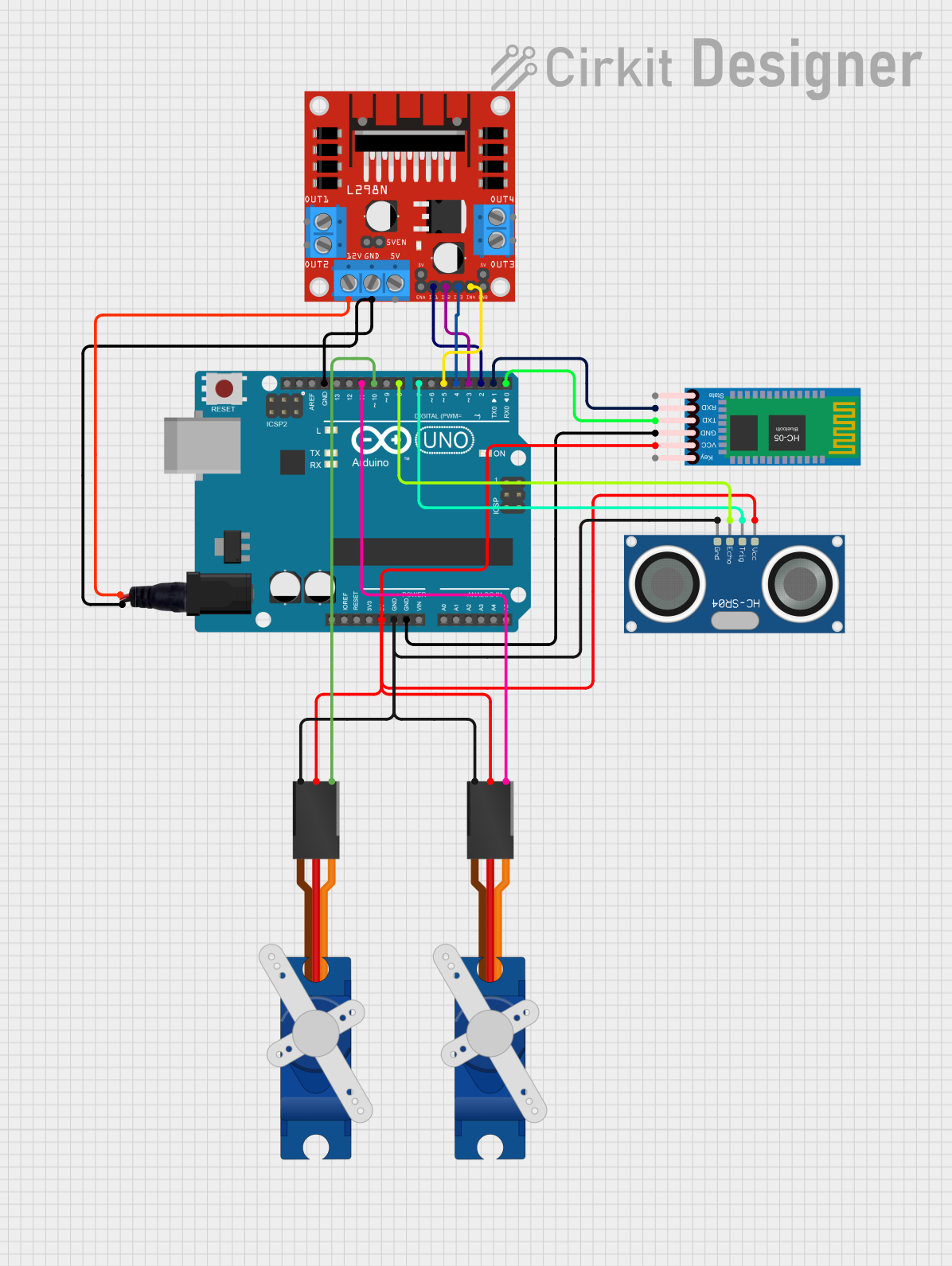
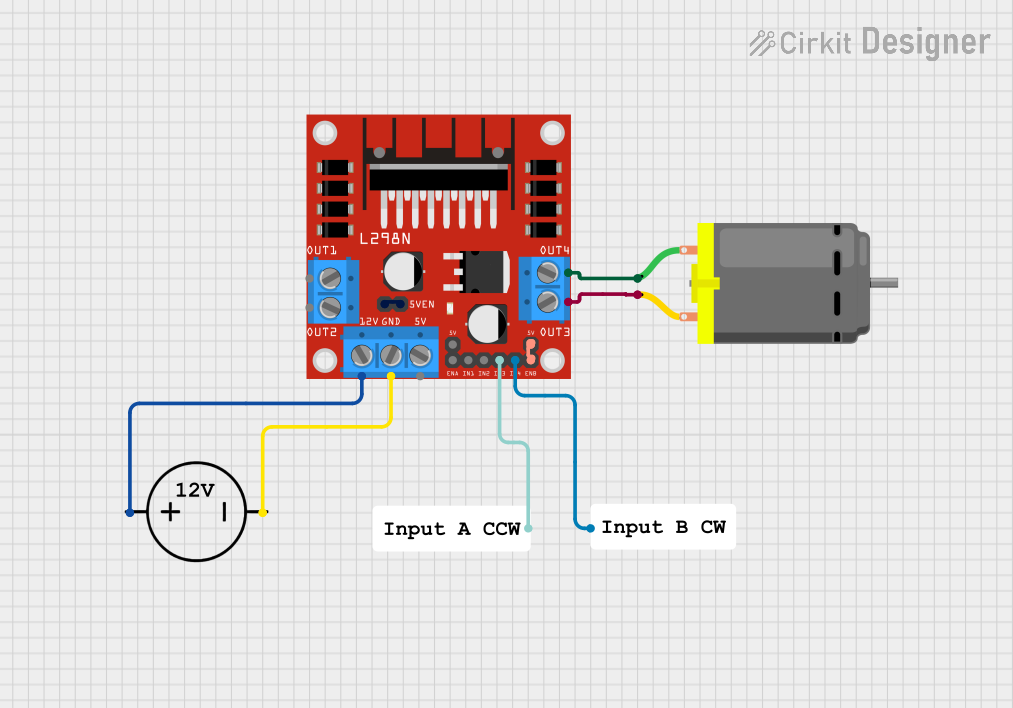

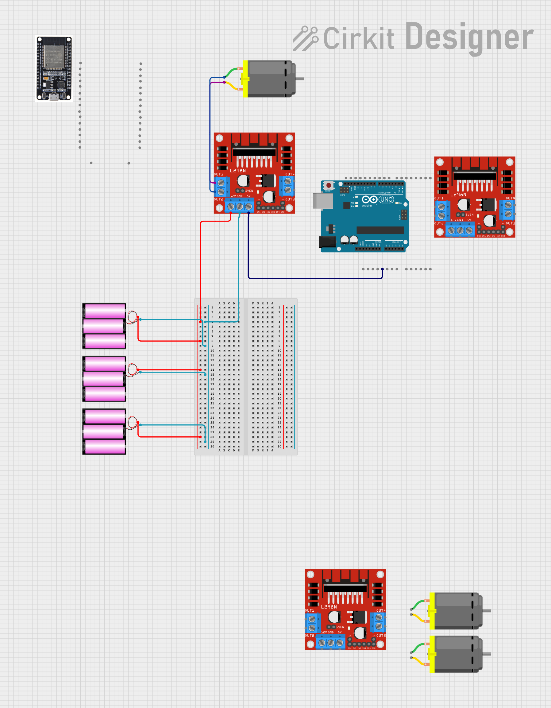
Explore Projects Built with Motor Driver (L298N)
Technical Specifications
Key Technical Details
| Parameter | Value |
|---|---|
| Operating Voltage | 5V to 35V |
| Output Current | 2A per channel (max) |
| Peak Output Current | 3A per channel (non-repetitive) |
| Control Logic Voltage | 5V |
| Power Dissipation | 25W |
| Operating Temperature | -25°C to +130°C |
| Dimensions | 43mm x 43mm x 27mm |
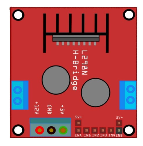
Pin Configuration and Descriptions
Power and Motor Connections
| Pin Name | Description |
|---|---|
| VCC | Motor power supply (5V to 35V) |
| GND | Ground |
| 5V | Logic power supply (5V) |
| OUT1 | Output to Motor A (Terminal 1) |
| OUT2 | Output to Motor A (Terminal 2) |
| OUT3 | Output to Motor B (Terminal 1) |
| OUT4 | Output to Motor B (Terminal 2) |
Control Pins
| Pin Name | Description |
|---|---|
| ENA | Enable pin for Motor A (PWM input) |
| IN1 | Control input 1 for Motor A |
| IN2 | Control input 2 for Motor A |
| ENB | Enable pin for Motor B (PWM input) |
| IN3 | Control input 1 for Motor B |
| IN4 | Control input 2 for Motor B |
Usage Instructions
How to Use the Component in a Circuit
Power Connections:
- Connect the VCC pin to the motor power supply (5V to 35V).
- Connect the GND pin to the ground of the power supply.
- Connect the 5V pin to the 5V output of the microcontroller (e.g., Arduino).
Motor Connections:
- Connect the motor terminals to OUT1 and OUT2 for Motor A.
- Connect the motor terminals to OUT3 and OUT4 for Motor B.
Control Connections:
- Connect the ENA pin to a PWM-capable pin on the microcontroller to control the speed of Motor A.
- Connect the IN1 and IN2 pins to digital pins on the microcontroller to control the direction of Motor A.
- Connect the ENB pin to a PWM-capable pin on the microcontroller to control the speed of Motor B.
- Connect the IN3 and IN4 pins to digital pins on the microcontroller to control the direction of Motor B.
Important Considerations and Best Practices
- Ensure that the power supply voltage does not exceed the maximum rating of 35V.
- Use appropriate heat sinks or cooling mechanisms if the module is expected to operate at high currents for extended periods.
- Double-check all connections before powering up the module to avoid damage to the components.
Example Code for Arduino UNO
// Define motor control pins
#define ENA 9
#define IN1 8
#define IN2 7
#define ENB 10
#define IN3 12
#define IN4 11

void setup() {
  // Set all the motor control pins to outputs
  pinMode(ENA, OUTPUT);
  pinMode(IN1, OUTPUT);
  pinMode(IN2, OUTPUT);
  pinMode(ENB, OUTPUT);
  pinMode(IN3, OUTPUT);
  pinMode(IN4, OUTPUT);
}

void loop() {
  // Example: Rotate Motor A forward at full speed
  digitalWrite(IN1, HIGH);
  digitalWrite(IN2, LOW);
  analogWrite(ENA, 255); // Full speed

  // Example: Rotate Motor B backward at half speed
  digitalWrite(IN3, LOW);
  digitalWrite(IN4, HIGH);
  analogWrite(ENB, 128); // Half speed

  delay(2000); // Run motors for 2 seconds

  // Stop both motors
  analogWrite(ENA, 0);
  analogWrite(ENB, 0);

  delay(2000); // Wait for 2 seconds
}
Troubleshooting and FAQs
Common Issues Users Might Face
Motor Not Running:
- Solution: Check all power and control connections. Ensure that the power supply voltage is within the specified range. Verify that the control signals from the microcontroller are correctly configured.
Overheating:
- Solution: Ensure that the current drawn by the motors does not exceed the maximum rating of 2A per channel. Use heat sinks or cooling mechanisms if necessary.
Erratic Motor Behavior:
- Solution: Check for loose connections or faulty wiring. Ensure that the control signals are stable and correctly timed.
FAQs
Can I control more than two motors with a single L298N module?
- No, the L298N module is designed to control up to two DC motors or one stepper motor.
What is the maximum voltage I can use with the L298N module?
- The maximum motor power supply voltage is 35V.
Can I use the L298N module with a Raspberry Pi?
- Yes, the L298N module can be used with a Raspberry Pi. Ensure that the control logic voltage is compatible (5V).
How do I control the speed of the motors?
- The speed of the motors can be controlled using PWM signals on the ENA and ENB pins.
By following this documentation, users should be able to effectively utilize the L298N Motor Driver in their projects, ensuring reliable and efficient motor control.