Cirkit Designer
Your all-in-one circuit design IDE
Home /
Component Documentation
How to Use OLED: Examples, Pinouts, and Specs
Introduction
An Organic Light Emitting Diode (OLED) is a type of display technology that uses organic compounds to emit light when an electric current is applied. It is known for its high contrast ratios, deep blacks, and wide viewing angles. OLED displays are commonly used in various applications, including:
- Wearable devices (smartwatches, fitness trackers)
- Consumer electronics (smartphones, tablets)
- Industrial and medical equipment
- Automotive displays
- DIY electronics projects
Explore Projects Built with OLED
IoT Board with 0.96" OLED Display for Real-Time Data Visualization

This circuit connects a 0.96" OLED display to an IoT board. The OLED display is powered by the 3.3V and GND pins of the IoT board, and communicates with the board via I2C using the SDA and SCL pins.
Arduino 101 OLED Display Animation Project

This circuit consists of an Arduino 101 microcontroller connected to a 0.96" OLED display via I2C communication. The Arduino runs a program that initializes the OLED and continuously displays an animated sequence of frames on the screen.
Wi-Fi Controlled RGB LED and OLED Display with ESP8266

This circuit features an ESP8266 microcontroller interfaced with a 128x64 OLED display via I2C for visual output and an RGB LED controlled through current-limiting resistors. The ESP8266 provides power and control signals to both the display and the LED, enabling visual feedback and status indication.
Arduino Nano and OLED Display for Real-Time Data Visualization

This circuit consists of an Arduino Nano microcontroller connected to a 0.96" OLED display. The Arduino Nano provides power to the OLED display and communicates with it using the I2C protocol via the A4 (SDA) and A5 (SCK) pins.
Explore Projects Built with OLED
IoT Board with 0.96" OLED Display for Real-Time Data Visualization
This circuit connects a 0.96" OLED display to an IoT board. The OLED display is powered by the 3.3V and GND pins of the IoT board, and communicates with the board via I2C using the SDA and SCL pins.
Arduino 101 OLED Display Animation Project
This circuit consists of an Arduino 101 microcontroller connected to a 0.96" OLED display via I2C communication. The Arduino runs a program that initializes the OLED and continuously displays an animated sequence of frames on the screen.
Wi-Fi Controlled RGB LED and OLED Display with ESP8266
This circuit features an ESP8266 microcontroller interfaced with a 128x64 OLED display via I2C for visual output and an RGB LED controlled through current-limiting resistors. The ESP8266 provides power and control signals to both the display and the LED, enabling visual feedback and status indication.
Arduino Nano and OLED Display for Real-Time Data Visualization
This circuit consists of an Arduino Nano microcontroller connected to a 0.96" OLED display. The Arduino Nano provides power to the OLED display and communicates with it using the I2C protocol via the A4 (SDA) and A5 (SCK) pins.
Technical Specifications
Key Technical Details
| Parameter | Value |
|---|---|
| Display Type | OLED |
| Resolution | 128x64 pixels |
| Interface | I2C / SPI |
| Operating Voltage | 3.3V - 5V |
| Current Consumption | 20mA (typical) |
| Viewing Angle | >160 degrees |
| Operating Temperature | -40°C to 85°C |
| Dimensions | 27.0mm x 27.0mm x 4.1mm |
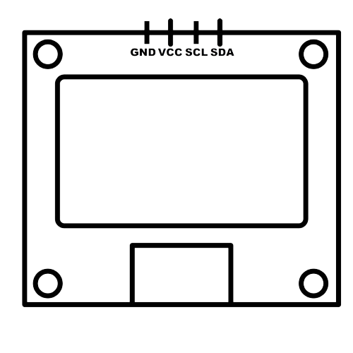
Pin Configuration and Descriptions
I2C Interface
| Pin Number | Pin Name | Description |
|---|---|---|
| 1 | GND | Ground |
| 2 | VCC | Power Supply (3.3V - 5V) |
| 3 | SCL | Serial Clock Line |
| 4 | SDA | Serial Data Line |
SPI Interface
| Pin Number | Pin Name | Description |
|---|---|---|
| 1 | GND | Ground |
| 2 | VCC | Power Supply (3.3V - 5V) |
| 3 | SCK | Serial Clock |
| 4 | MOSI | Master Out Slave In |
| 5 | RES | Reset |
| 6 | DC | Data/Command |
| 7 | CS | Chip Select |
Usage Instructions
How to Use the Component in a Circuit
Connecting to an Arduino UNO (I2C Interface)
- Connect the GND pin of the OLED to the GND pin of the Arduino.
- Connect the VCC pin of the OLED to the 5V pin of the Arduino.
- Connect the SCL pin of the OLED to the A5 pin of the Arduino.
- Connect the SDA pin of the OLED to the A4 pin of the Arduino.
Sample Code for Arduino UNO
#include <Wire.h>
#include <Adafruit_GFX.h>
#include <Adafruit_SSD1306.h>

// Define the OLED reset pin
#define OLED_RESET -1

// Create an instance of the SSD1306 display
Adafruit_SSD1306 display(OLED_RESET);

void setup() {
  // Initialize the display
  if(!display.begin(SSD1306_I2C_ADDRESS, OLED_RESET)) {
    Serial.println(F("SSD1306 allocation failed"));
    for(;;);
  }
  display.display();
  delay(2000); // Pause for 2 seconds

  // Clear the buffer
  display.clearDisplay();

  // Display text
  display.setTextSize(1);
  display.setTextColor(SSD1306_WHITE);
  display.setCursor(0,0);
  display.println(F("Hello, world!"));
  display.display();
}

void loop() {
  // Add your main code here, to run repeatedly
}
Important Considerations and Best Practices
- Ensure that the power supply voltage matches the operating voltage of the OLED (3.3V - 5V).
- Avoid exposing the OLED display to static electricity, which can damage the component.
- Handle the OLED display with care to prevent damage to the screen and connectors.
- Use appropriate libraries (e.g., Adafruit_SSD1306) to simplify the integration and control of the OLED display.
Troubleshooting and FAQs
Common Issues Users Might Face
Display Not Turning On
- Solution: Check the power connections and ensure the correct voltage is supplied.
- Solution: Verify the I2C/SPI connections and ensure they are properly connected.
Garbled or Noisy Display
- Solution: Ensure that the data and clock lines are properly connected and not loose.
- Solution: Check for any loose connections or short circuits.
Partial Display or Missing Pixels
- Solution: Verify that the display initialization code is correct.
- Solution: Ensure that the display buffer is being properly updated.
Tips for Troubleshooting
- Double-check all wiring connections and ensure they match the pin configuration.
- Use a multimeter to verify the voltage levels at the OLED pins.
- Test the OLED display with a simple example code to ensure it is functioning correctly.
- Consult the datasheet and library documentation for additional troubleshooting steps.
By following this documentation, users should be able to effectively integrate and utilize the OLED display module in their projects, whether they are beginners or experienced electronics enthusiasts.