How to Use PCF8574T I2C: Examples, Pinouts, and Specs
Introduction
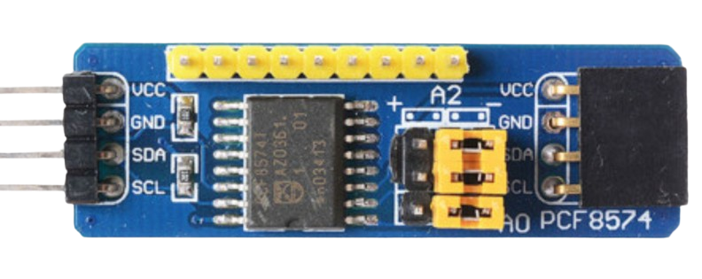
The PCF8574T is an I2C I/O expander that allows for the addition of 8 digital input/output (GPIO) pins to a microcontroller via the I2C bus. This component is particularly useful in embedded systems where the number of available GPIO pins is limited. By utilizing the I2C protocol, the PCF8574T enables efficient communication with minimal pin usage, requiring only two lines: SDA (data) and SCL (clock).
Explore Projects Built with PCF8574T I2C


Explore Projects Built with PCF8574T I2C
Common Applications and Use Cases
- Expanding GPIO pins in microcontroller-based projects
- Driving LEDs, relays, or other digital outputs
- Reading digital inputs such as switches or sensors
- Interfacing with LCD displays (e.g., 16x2 or 20x4 character displays)
- Home automation and IoT devices
Technical Specifications
The following table outlines the key technical details of the PCF8574T:
| Parameter | Value |
|---|---|
| Operating Voltage | 2.5V to 6V |
| Maximum Sink Current | 25 mA per pin |
| Maximum Source Current | -300 µA per pin |
| I2C Address Range | 0x20 to 0x27 (configurable) |
| Communication Protocol | I2C (up to 100 kHz) |
| Number of I/O Pins | 8 |
| Package Type | SOIC-16, DIP-16 |
| Operating Temperature | -40°C to +85°C |
Pin Configuration and Descriptions
The PCF8574T has 16 pins, as described in the table below:
| Pin Number | Pin Name | Description |
|---|---|---|
| 1 | P0 | GPIO Pin 0 (bidirectional) |
| 2 | P1 | GPIO Pin 1 (bidirectional) |
| 3 | P2 | GPIO Pin 2 (bidirectional) |
| 4 | P3 | GPIO Pin 3 (bidirectional) |
| 5 | P4 | GPIO Pin 4 (bidirectional) |
| 6 | P5 | GPIO Pin 5 (bidirectional) |
| 7 | P6 | GPIO Pin 6 (bidirectional) |
| 8 | P7 | GPIO Pin 7 (bidirectional) |
| 9 | GND | Ground |
| 10 | INT | Interrupt Output (active low) |
| 11 | SCL | I2C Clock Line |
| 12 | SDA | I2C Data Line |
| 13 | A0 | Address Selection Bit 0 |
| 14 | A1 | Address Selection Bit 1 |
| 15 | A2 | Address Selection Bit 2 |
| 16 | VCC | Power Supply (2.5V to 6V) |
Usage Instructions
How to Use the PCF8574T in a Circuit
- Power Supply: Connect the VCC pin to a 3.3V or 5V power source and the GND pin to ground.
- I2C Connections: Connect the SDA and SCL pins to the corresponding I2C pins on your microcontroller. Pull-up resistors (typically 4.7kΩ) are required on the SDA and SCL lines.
- Address Configuration: Set the I2C address by connecting the A0, A1, and A2 pins to either VCC (logic high) or GND (logic low). This allows for up to 8 devices on the same I2C bus.
- GPIO Usage: Use the P0–P7 pins as digital inputs or outputs. When configured as outputs, the pins can sink up to 25 mA, making them suitable for driving LEDs or relays.
Important Considerations and Best Practices
- Interrupt Pin: The INT pin can be used to detect changes on input pins. It is active low and should be connected to an interrupt-capable pin on the microcontroller.
- Current Limitations: Avoid exceeding the maximum sink current of 25 mA per pin to prevent damage to the device.
- I2C Pull-Up Resistors: Ensure proper pull-up resistors are used on the SDA and SCL lines for reliable communication.
- Address Conflicts: If using multiple PCF8574T devices, ensure each has a unique I2C address by configuring the A0, A1, and A2 pins appropriately.
Example Code for Arduino UNO
Below is an example of how to use the PCF8574T with an Arduino UNO to toggle an LED connected to pin P0:
#include <Wire.h> // Include the Wire library for I2C communication

#define PCF8574_ADDRESS 0x20 // Default I2C address of the PCF8574T

void setup() {
  Wire.begin(); // Initialize I2C communication
  Serial.begin(9600); // Initialize serial communication for debugging

  // Set all pins of PCF8574T to HIGH (default state)
  Wire.beginTransmission(PCF8574_ADDRESS);
  Wire.write(0xFF); // All pins HIGH
  Wire.endTransmission();

  Serial.println("PCF8574T initialized.");
}

void loop() {
  // Toggle P0 (connected to an LED)
  Wire.beginTransmission(PCF8574_ADDRESS);
  Wire.write(0xFE); // Set P0 LOW, others HIGH
  Wire.endTransmission();
  delay(500); // Wait for 500ms

  Wire.beginTransmission(PCF8574_ADDRESS);
  Wire.write(0xFF); // Set P0 HIGH, others HIGH
  Wire.endTransmission();
  delay(500); // Wait for 500ms
}
Troubleshooting and FAQs
Common Issues and Solutions
No Response from the PCF8574T
- Cause: Incorrect I2C address or wiring.
- Solution: Verify the I2C address and ensure proper connections for SDA, SCL, VCC, and GND.
I2C Communication Errors
- Cause: Missing or incorrect pull-up resistors on SDA and SCL lines.
- Solution: Add 4.7kΩ pull-up resistors to SDA and SCL.
GPIO Pins Not Responding
- Cause: Exceeding current limits or incorrect configuration.
- Solution: Check the current requirements of connected devices and ensure proper pin configuration.
Interrupt Pin Not Working
- Cause: INT pin not connected or not configured correctly.
- Solution: Connect the INT pin to an interrupt-capable pin on the microcontroller and configure it in the code.
FAQs
Q: Can the PCF8574T be used with 3.3V systems?
- A: Yes, the PCF8574T operates with voltages as low as 2.5V, making it compatible with 3.3V systems.
Q: How many PCF8574T devices can be connected to the same I2C bus?
- A: Up to 8 devices can be connected by configuring the A0, A1, and A2 pins for unique addresses.
Q: Can the PCF8574T drive high-current devices like motors?
- A: No, the PCF8574T is not designed for high-current applications. Use a transistor or relay for such devices.