How to Use OLED: Examples, Pinouts, and Specs
Introduction
An Organic Light Emitting Diode (OLED) is a display technology that uses organic compounds to emit light when an electric current is applied. Unlike traditional LCDs, OLEDs do not require a backlight, allowing for thinner, more energy-efficient displays with superior image quality. Manufactured by Pololu, this OLED module is designed for use in a variety of electronic projects, offering high contrast ratios, vibrant colors, and deep blacks.
Explore Projects Built with OLED


Explore Projects Built with OLED
Common Applications and Use Cases
- Wearable devices and smartwatches
- Portable electronic displays
- IoT devices and dashboards
- Arduino and microcontroller-based projects
- Consumer electronics such as smartphones and MP3 players
Technical Specifications
The Pololu OLED module is designed for ease of use and compatibility with microcontrollers like Arduino. Below are the key technical details:
General Specifications
| Parameter | Value |
|---|---|
| Display Type | OLED |
| Resolution | 128 x 64 pixels |
| Interface | I2C or SPI |
| Operating Voltage | 3.3V to 5V |
| Current Consumption | ~20mA (typical) |
| Dimensions | 27mm x 27mm x 4mm |
| Viewing Angle | ~160° |
| Manufacturer | Pololu |
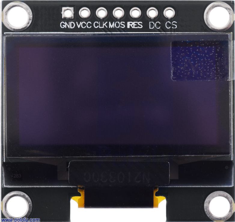
Pin Configuration
The Pololu OLED module has a simple pinout for easy integration. Below is the pin configuration:
| Pin Number | Pin Name | Description |
|---|---|---|
| 1 | GND | Ground connection |
| 2 | VCC | Power supply (3.3V or 5V) |
| 3 | SCL | Serial Clock Line for I2C or SPI Clock |
| 4 | SDA | Serial Data Line for I2C or SPI Data |
| 5 | RES | Reset pin (active low) |
| 6 | DC | Data/Command control pin (used in SPI mode) |
| 7 | CS | Chip Select (used in SPI mode) |
Usage Instructions
Connecting the OLED to an Arduino UNO
To use the Pololu OLED module with an Arduino UNO, follow these steps:
Wiring: Connect the OLED module to the Arduino as shown below:
- GND → GND
- VCC → 5V
- SCL → A5 (for I2C) or D13 (for SPI)
- SDA → A4 (for I2C) or D11 (for SPI)
- RES → D8
- DC → D9 (SPI only)
- CS → D10 (SPI only)
Install Libraries: Install the
Adafruit_GFXandAdafruit_SSD1306libraries in the Arduino IDE. These libraries provide functions for controlling the OLED.Upload Code: Use the following example code to display text on the OLED:
#include <Wire.h>                // Library for I2C communication
#include <Adafruit_GFX.h>        // Graphics library for OLED
#include <Adafruit_SSD1306.h>    // OLED driver library

#define SCREEN_WIDTH 128         // OLED display width, in pixels
#define SCREEN_HEIGHT 64         // OLED display height, in pixels

// Create an SSD1306 display object connected to I2C (SDA, SCL)
Adafruit_SSD1306 display(SCREEN_WIDTH, SCREEN_HEIGHT, &Wire, -1);

void setup() {
  // Initialize the display
  if (!display.begin(SSD1306_I2C_ADDRESS, 0x3C)) {
    Serial.println(F("SSD1306 allocation failed"));
    for (;;); // Loop forever if initialization fails
  }

  display.clearDisplay();        // Clear the display buffer
  display.setTextSize(1);        // Set text size to 1 (smallest)
  display.setTextColor(SSD1306_WHITE); // Set text color to white
  display.setCursor(0, 0);       // Set cursor to top-left corner
  display.println(F("Hello, OLED!")); // Print text to the buffer
  display.display();             // Display the buffer on the screen
}

void loop() {
  // Nothing to do here
}
Important Considerations and Best Practices
- Power Supply: Ensure the OLED module is powered within its operating voltage range (3.3V to 5V).
- I2C Address: The default I2C address for most OLED modules is
0x3C. Verify this in the datasheet or by scanning I2C devices. - Reset Pin: Connect the RES pin to a digital pin on the microcontroller for proper initialization.
- Contrast Settings: Adjust the contrast settings in the library if the display appears too dim or too bright.
Troubleshooting and FAQs
Common Issues
The OLED does not turn on:
- Verify all connections are secure and correct.
- Ensure the power supply voltage is within the specified range.
- Check if the I2C address matches the one in the code.
The display shows random pixels or is blank:
- Ensure the RES pin is properly connected and initialized in the code.
- Confirm that the correct library is installed and used.
Text or graphics appear distorted:
- Check the resolution settings in the code (
SCREEN_WIDTHandSCREEN_HEIGHT). - Ensure the correct communication protocol (I2C or SPI) is selected.
- Check the resolution settings in the code (
Tips for Troubleshooting
- Use an I2C scanner sketch to detect the OLED module's address.
- Test the module with a simple "Hello World" sketch before implementing complex graphics.
- If using SPI, ensure the CS, DC, and RES pins are correctly defined in the code.
By following this documentation, you can successfully integrate and use the Pololu OLED module in your projects.