How to Use SparkFun AST-CAN485 Wifi Shield: Examples, Pinouts, and Specs
Introduction
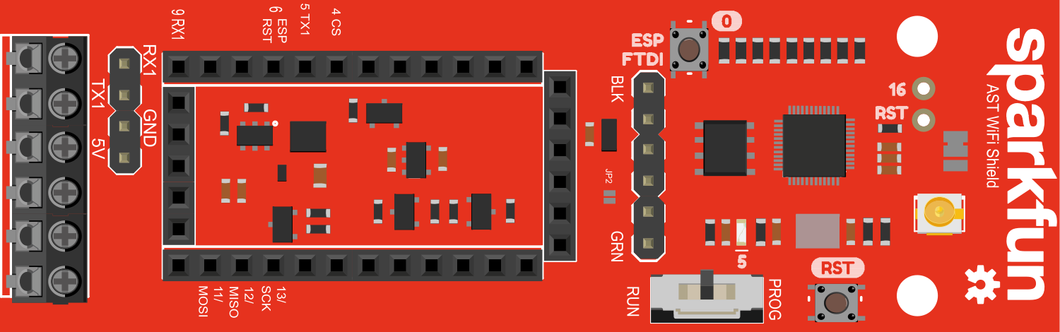
The SparkFun AST-CAN485 WiFi Shield is an innovative communication module that integrates WiFi connectivity with CAN (Controller Area Network) and RS-485 protocols. This shield is designed to be compatible with the Arduino UNO form factor, enabling users to add wireless communication capabilities to their projects with ease. It is particularly useful for applications in automation, automotive systems, and industrial control where robust and reliable communication is essential.
Explore Projects Built with SparkFun AST-CAN485 Wifi Shield

Explore Projects Built with SparkFun AST-CAN485 Wifi Shield
Common Applications and Use Cases
- Industrial automation systems
- Automotive diagnostics and networking
- Remote sensor monitoring
- Home automation
- Robotics
Technical Specifications
Key Technical Details
- Operating Voltage: 3.3V to 5V
- WiFi: ESP8266 module for 802.11 b/g/n
- CAN Bus: MCP2515 CAN controller with MCP2551 CAN transceiver
- RS-485: SP3485 transceiver
- Logic Level: 3.3V (5V tolerant inputs)
- Current Rating: 500 mA (max for WiFi module)
Pin Configuration and Descriptions
| Pin Number | Function | Description |
|---|---|---|
| D0 | RX | UART Receive pin |
| D1 | TX | UART Transmit pin |
| D2 | INT | Interrupt pin for CAN controller |
| D10 | CS | Chip Select for CAN controller |
| D11 | MOSI | SPI communication (Master Out Slave In) |
| D12 | MISO | SPI communication (Master In Slave Out) |
| D13 | SCK | SPI communication (Serial Clock) |
| A0 | RS-485 A | RS-485 A-line (non-inverting) |
| A1 | RS-485 B | RS-485 B-line (inverting) |
| VIN | Voltage Input | Input voltage for the shield (5V recommended) |
| 3V3 | 3.3V Output | 3.3V output from the onboard voltage regulator |
| GND | Ground | Ground connection |
Usage Instructions
How to Use the Component in a Circuit
- Mounting the Shield: Attach the SparkFun AST-CAN485 WiFi Shield onto an Arduino UNO ensuring proper alignment of pins.
- Power Supply: Connect a 5V power supply to the VIN pin or power the Arduino UNO via its USB connection.
- Programming: Use the Arduino IDE to program the Arduino UNO with the necessary code to control the shield.
- WiFi Configuration: Set up the ESP8266 module by configuring the SSID and password for network connectivity.
- CAN/RS-485 Configuration: Initialize the CAN or RS-485 module depending on the communication protocol required for your application.
Important Considerations and Best Practices
- Ensure that the power supply is sufficient for both the Arduino UNO and the WiFi shield.
- Use proper ESD precautions when handling the shield to prevent damage to sensitive components.
- When using RS-485 communication, ensure that the A and B lines are connected correctly to avoid communication errors.
- For CAN communication, termination resistors may be necessary depending on the network design.
Troubleshooting and FAQs
Common Issues Users Might Face
- WiFi Connectivity Issues: Ensure that the network credentials are correctly entered and that the ESP8266 module is properly initialized in the code.
- CAN Bus Communication Failure: Check the wiring and termination resistors on the CAN network. Ensure that the baud rate is correctly set.
- RS-485 Signal Distortion: Verify the cable length and integrity. Ensure that the A and B lines are not reversed.
Solutions and Tips for Troubleshooting
- Reset the Shield: Sometimes simply resetting the shield and Arduino can resolve communication issues.
- Serial Monitor: Use the Arduino's serial monitor to debug and monitor the status of WiFi, CAN, and RS-485 communications.
- Update Firmware: Ensure that the latest firmware is installed on the ESP8266 module for optimal performance.
Example Code for Arduino UNO
#include <SPI.h>
#include <ESP8266WiFi.h>

// Replace with your network credentials
const char* ssid = "yourSSID";
const char* password = "yourPASSWORD";

void setup() {
  Serial.begin(115200); // Start serial communication at 115200 baud
  WiFi.begin(ssid, password); // Connect to WiFi network

  while (WiFi.status() != WL_CONNECTED) {
    delay(500);
    Serial.print(".");
  }
  Serial.println("");
  Serial.println("WiFi connected");
}

void loop() {
  // Your code here to handle CAN/RS-485 communication
}
Note: This example demonstrates how to connect to a WiFi network using the ESP8266 module on the SparkFun AST-CAN485 WiFi Shield. Additional code is required to handle CAN or RS-485 communication, which will depend on the specific requirements of your project.
Remember to adhere to the 80 character line length limit for code comments, wrapping text as necessary. This ensures readability and maintainability of the code.