How to Use Full Bridge Rectifier: Examples, Pinouts, and Specs
Introduction
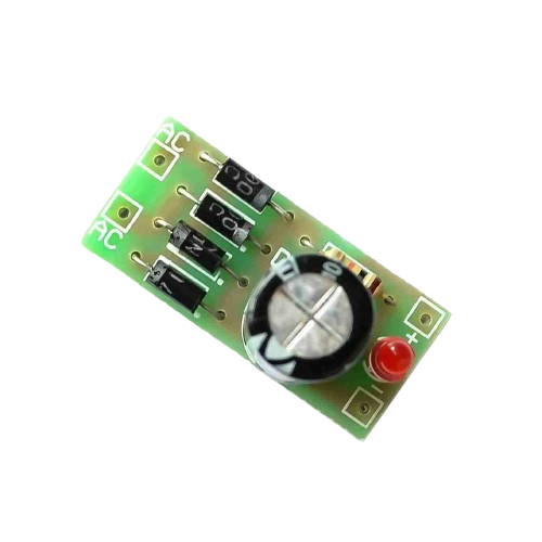
A full bridge rectifier is an electrical circuit consisting of four diodes arranged in a bridge configuration to convert alternating current (AC) input into direct current (DC) output. This component is essential in power supply units, allowing AC from the mains to be converted into a usable DC form for electronic devices. Common applications include power adapters, battery charging circuits, and DC motor drives.
Explore Projects Built with Full Bridge Rectifier
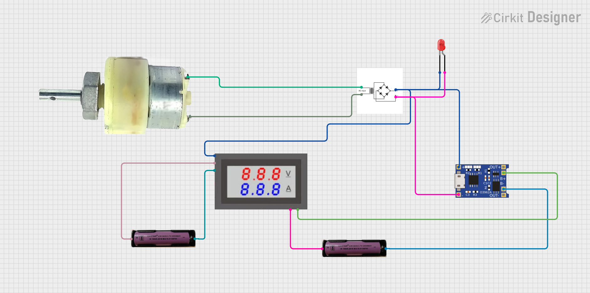
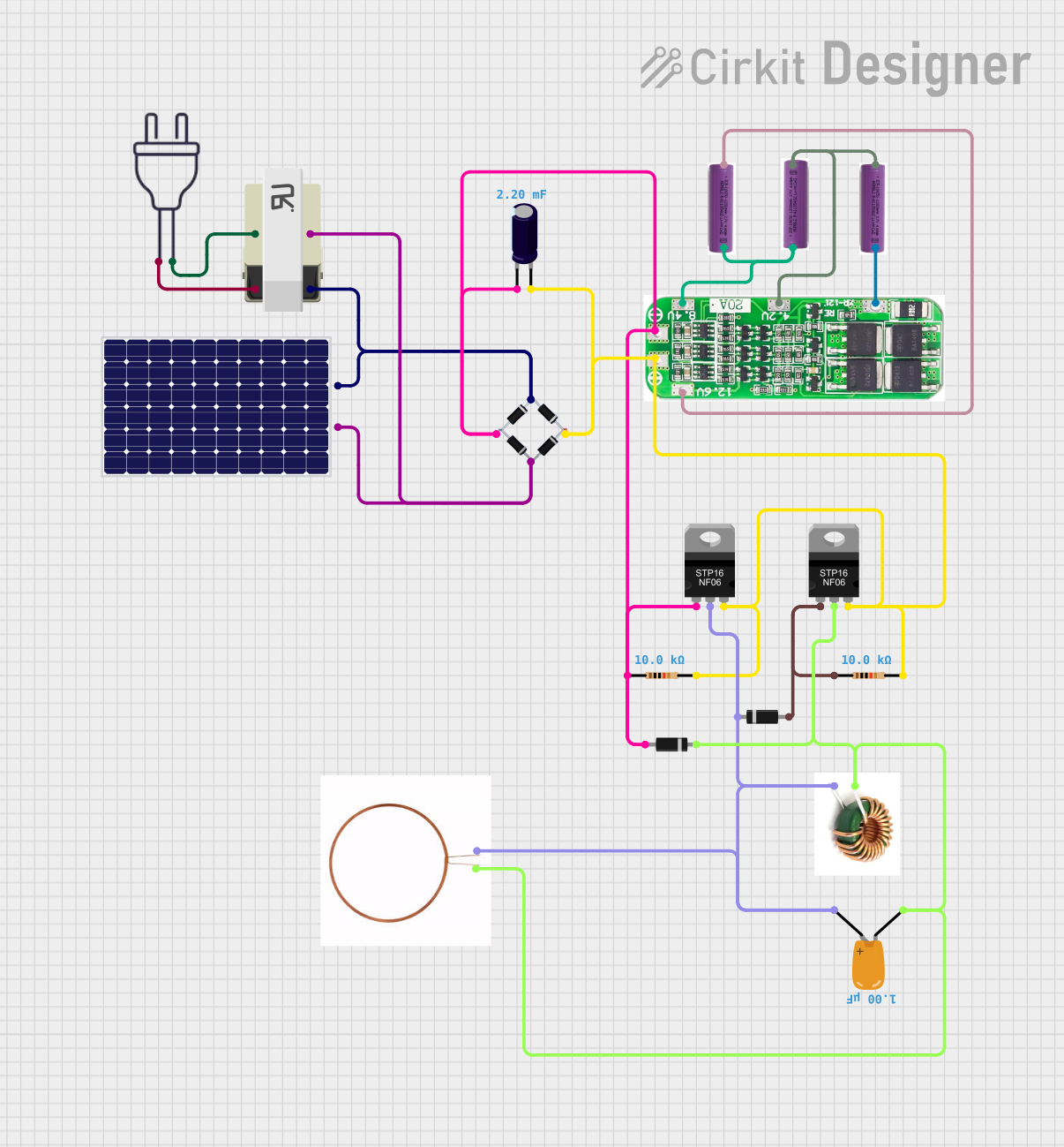

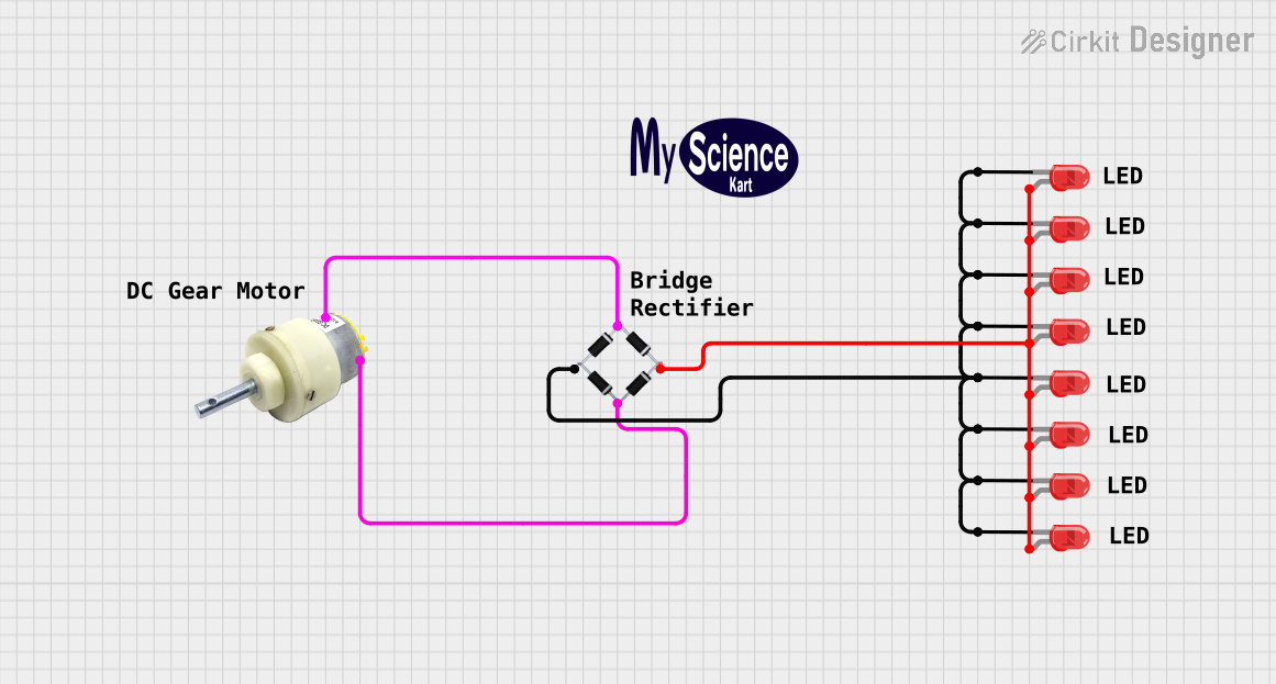
Explore Projects Built with Full Bridge Rectifier
Technical Specifications
Key Technical Details
| Parameter | Value |
|---|---|
| Input Voltage | 100V - 240V AC |
| Output Voltage | Depends on input and load |
| Maximum Current | 1A - 50A (varies by model) |
| Power Rating | Up to 1000W (varies by model) |
| Diode Type | Silicon |
| Efficiency | Typically 80% - 90% |
| Temperature Range | -40°C to 150°C |
Pin Configuration and Descriptions
| Pin Number | Pin Name | Description |
|---|---|---|
| 1 | AC1 | AC input terminal 1 |
| 2 | AC2 | AC input terminal 2 |
| 3 | DC+ | Positive DC output terminal |
| 4 | DC- | Negative DC output terminal |
Usage Instructions
How to Use the Component in a Circuit
Connect the AC Input:
- Connect the AC1 and AC2 pins to the AC source. Ensure the voltage rating of the rectifier matches the AC source.
Connect the DC Output:
- Connect the DC+ and DC- pins to the load or the next stage of your circuit. The DC+ pin provides the positive voltage, and the DC- pin provides the ground.
Filtering:
- To smooth the rectified output, connect a capacitor across the DC+ and DC- terminals. The value of the capacitor depends on the load and desired ripple voltage.
Important Considerations and Best Practices
Heat Dissipation:
- Full bridge rectifiers can generate significant heat. Use appropriate heat sinks or cooling mechanisms to prevent overheating.
Current Rating:
- Ensure the rectifier's current rating exceeds the maximum current draw of your load to avoid damage.
Reverse Voltage Protection:
- Use diodes with a reverse voltage rating higher than the peak AC voltage to prevent breakdown.
Safety:
- Always handle AC connections with care. Ensure the circuit is powered off before making any connections.
Troubleshooting and FAQs
Common Issues Users Might Face
No DC Output:
- Solution: Check the AC input connections and ensure the AC source is functioning. Verify the diodes are not damaged.
Excessive Ripple in DC Output:
- Solution: Increase the value of the filtering capacitor. Ensure the capacitor is rated for the correct voltage.
Overheating:
- Solution: Use a heat sink or cooling fan. Ensure the rectifier is not overloaded beyond its current rating.
Low Efficiency:
- Solution: Check for any loose connections or damaged components. Ensure the diodes are of high quality and have low forward voltage drop.
FAQs
Q1: Can I use a full bridge rectifier with an Arduino UNO?
A1: Yes, you can use a full bridge rectifier to convert AC to DC, which can then be regulated to power the Arduino UNO. However, ensure the output voltage is within the acceptable range for the Arduino's input.
Q2: What type of capacitor should I use for filtering?
A2: Use an electrolytic capacitor with a voltage rating higher than the rectified DC voltage. The capacitance value depends on the load and desired ripple voltage, typically ranging from 100µF to 1000µF.
Q3: How do I calculate the output voltage of the rectifier?
A3: The output voltage (V_dc) can be approximated as V_dc ≈ V_ac_peak - 2 * V_d, where V_ac_peak is the peak AC voltage and V_d is the forward voltage drop of the diodes.
By following this documentation, users can effectively utilize a full bridge rectifier in their electronic projects, ensuring efficient and reliable AC to DC conversion.