
How to Use 1 Channel Relay 5V: Examples, Pinouts, and Specs
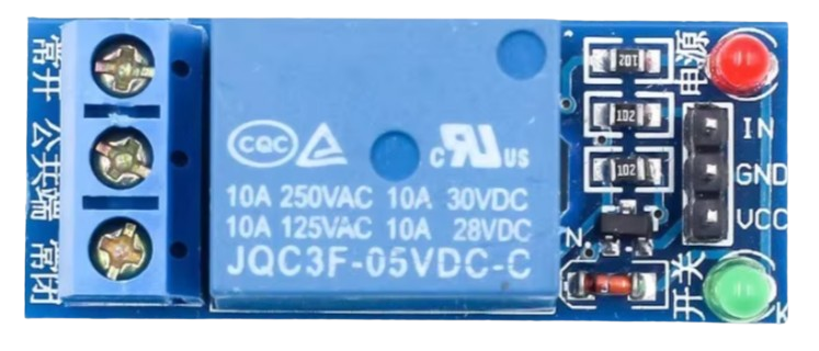
 Design with 1 Channel Relay 5V in Cirkit Designer
Introduction
The 1 Channel Relay 5V is an electromechanical switch module that allows a low voltage control signal (e.g., from a microcontroller) to control a higher voltage circuit. This module is widely used in automation, home appliances, and control systems to switch devices such as lights, fans, motors, or other high-power loads. It operates at 5V, making it compatible with most microcontrollers, including Arduino and Raspberry Pi.
Explore Projects Built with 1 Channel Relay 5V
 Open Project in Cirkit Designer
 Open Project in Cirkit Designer
 Open Project in Cirkit Designer
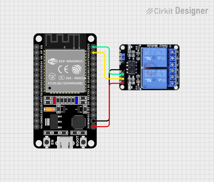 Open Project in Cirkit Designer
Explore Projects Built with 1 Channel Relay 5V
Open Project in Cirkit DesignerOpen Project in Cirkit DesignerOpen Project in Cirkit DesignerOpen Project in Cirkit DesignerCommon Applications
- Home automation systems (e.g., controlling lights or appliances)
- Industrial control systems
- Motor control
- IoT projects
- Security systems (e.g., activating alarms or locks)
Technical Specifications
Below are the key technical details of the 1 Channel Relay 5V module:
| Parameter | Value |
|---|---|
| Operating Voltage | 5V DC |
| Trigger Voltage | 3.3V to 5V |
| Maximum Load Voltage | 250V AC / 30V DC |
| Maximum Load Current | 10A |
| Relay Type | SPDT (Single Pole Double Throw) |
| Isolation | Optocoupler for signal isolation |
| Dimensions | ~50mm x 26mm x 18mm |
Pin Configuration
The 1 Channel Relay 5V module typically has the following pins:
| Pin Name | Description |
|---|---|
| VCC | Power supply input (5V DC) |
| GND | Ground connection |
| IN | Control signal input (connect to microcontroller GPIO pin) |
| COM | Common terminal for the relay switch |
| NO | Normally Open terminal (connected to COM when the relay is activated) |
| NC | Normally Closed terminal (connected to COM when the relay is not activated) |
Usage Instructions
Connecting the Relay to a Circuit
- Power the Relay Module: Connect the
VCCpin to a 5V power source and theGNDpin to ground. - Control Signal: Connect the
INpin to a GPIO pin of your microcontroller (e.g., Arduino). - Load Connection:
- Connect the device you want to control (e.g., a light bulb) to the
COMandNOterminals if you want the device to turn on when the relay is activated. - Use the
COMandNCterminals if you want the device to turn off when the relay is activated.
- Connect the device you want to control (e.g., a light bulb) to the
- Microcontroller Setup: Program your microcontroller to send a HIGH or LOW signal to the
INpin to activate or deactivate the relay.
Important Considerations
- Isolation: The relay module uses an optocoupler for isolation, ensuring that the high-voltage circuit is electrically isolated from the low-voltage control circuit.
- Power Supply: Ensure the relay module is powered with a stable 5V DC supply.
- Load Ratings: Do not exceed the maximum load voltage (250V AC / 30V DC) or current (10A) to avoid damage.
- Flyback Diode: If controlling an inductive load (e.g., a motor), use a flyback diode across the load to protect the relay from voltage spikes.
Example: Using the Relay with Arduino UNO
Below is an example of how to control the 1 Channel Relay 5V module using an Arduino UNO:
// Define the pin connected to the relay module
const int relayPin = 7; // Connect the IN pin of the relay to Arduino pin 7

void setup() {
  pinMode(relayPin, OUTPUT); // Set the relay pin as an output
  digitalWrite(relayPin, LOW); // Ensure the relay is off at startup
}

void loop() {
  // Turn the relay ON
  digitalWrite(relayPin, HIGH); // Send a HIGH signal to activate the relay
  delay(5000); // Keep the relay ON for 5 seconds

  // Turn the relay OFF
  digitalWrite(relayPin, LOW); // Send a LOW signal to deactivate the relay
  delay(5000); // Keep the relay OFF for 5 seconds
}
Notes:
- Replace
relayPinwith the GPIO pin you are using if different from pin 7. - Ensure the Arduino is powered properly and shares a common ground with the relay module.
Troubleshooting and FAQs
Common Issues
Relay Not Activating:
- Ensure the
VCCandGNDpins are connected properly to a 5V power source. - Verify that the control signal voltage (on the
INpin) is within the acceptable range (3.3V to 5V). - Check for loose or incorrect wiring.
- Ensure the
Load Not Switching:
- Confirm that the load is connected to the correct terminals (
COM,NO, orNC). - Ensure the load does not exceed the relay's maximum voltage or current ratings.
- Check the external power supply for the load.
- Confirm that the load is connected to the correct terminals (
Relay Clicking but No Output:
- Verify the wiring of the high-voltage circuit.
- Inspect the relay module for physical damage or burnt components.
FAQs
Q: Can I use the relay module with a 3.3V microcontroller like ESP8266 or ESP32?
A: Yes, the relay module can be triggered with a 3.3V control signal. However, ensure the VCC pin is still powered with 5V.
Q: Is the relay safe for switching high-power devices?
A: Yes, as long as the device's voltage and current ratings are within the relay's specifications (250V AC / 30V DC, 10A max).
Q: Why is an optocoupler used in the relay module?
A: The optocoupler provides electrical isolation between the low-voltage control circuit and the high-voltage load circuit, enhancing safety and protecting the microcontroller.
Q: Can I control multiple relays with one microcontroller?
A: Yes, you can control multiple relay modules by connecting each IN pin to a separate GPIO pin on the microcontroller. Ensure the microcontroller can handle the total current draw of all connected relays.
By following this documentation, you can effectively use the 1 Channel Relay 5V module in your projects for safe and reliable control of high-voltage devices.