Cirkit Designer
Your all-in-one circuit design IDE
Home /
Component Documentation
How to Use DRV8833 Dual Motor Driver Carrier: Examples, Pinouts, and Specs
Introduction
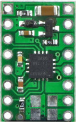
The DRV8833 Dual Motor Driver Carrier by Pololu is a compact and efficient motor driver board designed to control two DC motors or one stepper motor. It is capable of providing up to 1.2A continuous current per channel, making it suitable for a wide range of applications. The built-in protection features, such as over-current protection, under-voltage lockout, and thermal shutdown, ensure reliable operation even in demanding environments.
Explore Projects Built with DRV8833 Dual Motor Driver Carrier
ESP32 and nRF24L01 Wi-Fi Controlled Dual Motor System
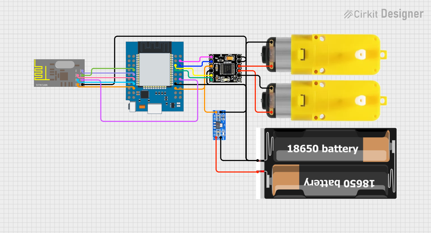
This circuit is a remote-controlled dual-motor driver system using an ESP32 microcontroller. The ESP32 interfaces with an nRF24L01 wireless module for communication and a DRV8833 motor driver to control two motors, powered by a 2x 18650 battery pack regulated by an AMS1117 voltage regulator.
Arduino Nano Motor Controller with DRV8833 Driver
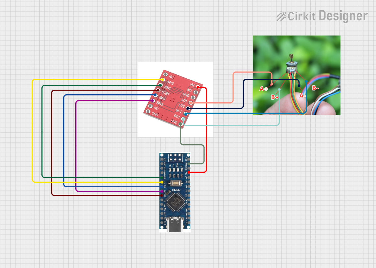
This circuit is designed to control a 2-phase 4-wire motor using an Arduino Nano 3.0 and a DRV8833 motor driver. The Arduino Nano provides control signals to the DRV8833, which in turn drives the motor, allowing for precise motor control.
ESP32 C3 Controlled Robot with VL6180 Time of Flight Sensor
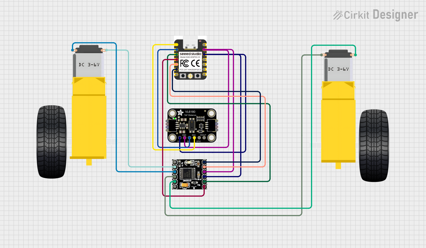
This circuit is designed to control a pair of DC gearmotors using a DRV8833 motor driver, with an ESP32 C3 microcontroller as the control unit. The microcontroller also interfaces with an Adafruit VL6180 Time of Flight sensor for distance measurement. The embedded code on the ESP32 C3 facilitates basic motor control (forward and backward) and reads distance data from the sensor, which is likely used for obstacle detection or range finding in a robotic application.
Battery-Powered Remote-Controlled Dual Motor System with Cytron URC10

This circuit is a remote-controlled dual DC motor driver system powered by a 3S LiPo battery. It uses a Cytron URC10 motor driver to control two GM25 DC motors based on signals received from an R6FG receiver, with a rocker switch for power control and a 7-segment panel voltmeter for monitoring the battery voltage.
Explore Projects Built with DRV8833 Dual Motor Driver Carrier
ESP32 and nRF24L01 Wi-Fi Controlled Dual Motor System
This circuit is a remote-controlled dual-motor driver system using an ESP32 microcontroller. The ESP32 interfaces with an nRF24L01 wireless module for communication and a DRV8833 motor driver to control two motors, powered by a 2x 18650 battery pack regulated by an AMS1117 voltage regulator.
Arduino Nano Motor Controller with DRV8833 Driver
This circuit is designed to control a 2-phase 4-wire motor using an Arduino Nano 3.0 and a DRV8833 motor driver. The Arduino Nano provides control signals to the DRV8833, which in turn drives the motor, allowing for precise motor control.
ESP32 C3 Controlled Robot with VL6180 Time of Flight Sensor
This circuit is designed to control a pair of DC gearmotors using a DRV8833 motor driver, with an ESP32 C3 microcontroller as the control unit. The microcontroller also interfaces with an Adafruit VL6180 Time of Flight sensor for distance measurement. The embedded code on the ESP32 C3 facilitates basic motor control (forward and backward) and reads distance data from the sensor, which is likely used for obstacle detection or range finding in a robotic application.
Battery-Powered Remote-Controlled Dual Motor System with Cytron URC10
This circuit is a remote-controlled dual DC motor driver system powered by a 3S LiPo battery. It uses a Cytron URC10 motor driver to control two GM25 DC motors based on signals received from an R6FG receiver, with a rocker switch for power control and a 7-segment panel voltmeter for monitoring the battery voltage.
Common Applications and Use Cases
- Robotics: Controlling the movement of small robots and robotic arms.
- Automated Systems: Driving motors in conveyor belts, automated doors, and other machinery.
- DIY Projects: Ideal for hobbyists building remote-controlled cars, boats, and other motorized projects.
- Educational Kits: Used in educational kits to teach students about motor control and electronics.
Technical Specifications
Key Technical Details
| Parameter | Value |
|---|---|
| Operating Voltage | 2.7V to 10.8V |
| Continuous Current | 1.2A per channel |
| Peak Current | 2A per channel |
| Control Interface | PWM (Pulse Width Modulation) |
| Built-in Protections | Over-current, under-voltage, thermal |
| Dimensions | 0.6" x 0.8" (15mm x 20mm) |
Pin Configuration and Descriptions
| Pin | Name | Description |
|---|---|---|
| 1 | VM | Motor power supply (2.7V to 10.8V) |
| 2 | GND | Ground |
| 3 | AIN1 | Control input for motor A (PWM or logic) |
| 4 | AIN2 | Control input for motor A (PWM or logic) |
| 5 | BIN1 | Control input for motor B (PWM or logic) |
| 6 | BIN2 | Control input for motor B (PWM or logic) |
| 7 | AO1 | Output for motor A |
| 8 | AO2 | Output for motor A |
| 9 | BO1 | Output for motor B |
| 10 | BO2 | Output for motor B |
| 11 | VCC | Logic power supply (2.7V to 5.5V) |
| 12 | nSLEEP | Sleep mode control (active low) |
| 13 | nFAULT | Fault indicator (active low) |
Usage Instructions
How to Use the Component in a Circuit
Power Supply:
- Connect the VM pin to the motor power supply (2.7V to 10.8V).
- Connect the VCC pin to the logic power supply (2.7V to 5.5V).
- Connect the GND pin to the ground of both power supplies.
Motor Connections:
- Connect the motor A to the AO1 and AO2 pins.
- Connect the motor B to the BO1 and BO2 pins.
Control Inputs:
- Use PWM signals or logic levels to control the AIN1, AIN2, BIN1, and BIN2 pins.
- To enable the driver, ensure the nSLEEP pin is pulled high.
Important Considerations and Best Practices
- Heat Dissipation: Ensure adequate ventilation or heat sinking if operating near the maximum current rating.
- Power Supply: Use a stable power supply to avoid voltage spikes that could trigger protection features.
- Decoupling Capacitors: Place decoupling capacitors close to the power supply pins to filter out noise.
- Fault Handling: Monitor the nFAULT pin to detect and handle fault conditions.
Example Code for Arduino UNO
// Example code to control two DC motors using DRV8833 and Arduino UNO

// Define motor control pins
const int AIN1 = 9;
const int AIN2 = 10;
const int BIN1 = 11;
const int BIN2 = 12;

void setup() {
  // Set motor control pins as outputs
  pinMode(AIN1, OUTPUT);
  pinMode(AIN2, OUTPUT);
  pinMode(BIN1, OUTPUT);
  pinMode(BIN2, OUTPUT);
}

void loop() {
  // Motor A forward
  digitalWrite(AIN1, HIGH);
  digitalWrite(AIN2, LOW);

  // Motor B forward
  digitalWrite(BIN1, HIGH);
  digitalWrite(BIN2, LOW);

  delay(1000); // Run motors for 1 second

  // Motor A backward
  digitalWrite(AIN1, LOW);
  digitalWrite(AIN2, HIGH);

  // Motor B backward
  digitalWrite(BIN1, LOW);
  digitalWrite(BIN2, HIGH);

  delay(1000); // Run motors for 1 second

  // Stop motors
  digitalWrite(AIN1, LOW);
  digitalWrite(AIN2, LOW);
  digitalWrite(BIN1, LOW);
  digitalWrite(BIN2, LOW);

  delay(1000); // Wait for 1 second
}
Troubleshooting and FAQs
Common Issues Users Might Face
Motors Not Running:
- Solution: Check power supply connections and ensure the nSLEEP pin is high.
Overheating:
- Solution: Ensure proper ventilation and consider adding a heat sink.
Fault Indicator Active (nFAULT pin low):
- Solution: Check for over-current, under-voltage, or thermal shutdown conditions.
Erratic Motor Behavior:
- Solution: Verify control signal integrity and ensure decoupling capacitors are in place.
Solutions and Tips for Troubleshooting
- Check Connections: Ensure all connections are secure and correct.
- Monitor Power Supply: Use a stable power supply and check for voltage drops.
- Use Proper Code: Ensure the control signals are correctly implemented in your code.
- Consult Datasheet: Refer to the DRV8833 datasheet for detailed information on protection features and operating conditions.
By following this documentation, users can effectively utilize the DRV8833 Dual Motor Driver Carrier in their projects, ensuring reliable and efficient motor control.