
How to Use Adafruit LIS3DH Triple-Axis Accelerometer: Examples, Pinouts, and Specs
 Design with Adafruit LIS3DH Triple-Axis Accelerometer in Cirkit Designer
Introduction
The Adafruit LIS3DH (Part ID: 2809) is a compact, low-power triple-axis accelerometer capable of measuring acceleration in three dimensions (X, Y, Z). It is widely used for motion detection, orientation sensing, and tilt measurement in a variety of applications. With its high-resolution output and versatile features, the LIS3DH is ideal for projects ranging from wearable devices to robotics and gaming controllers.
Explore Projects Built with Adafruit LIS3DH Triple-Axis Accelerometer
 Open Project in Cirkit Designer
 Open Project in Cirkit Designer
 Open Project in Cirkit Designer
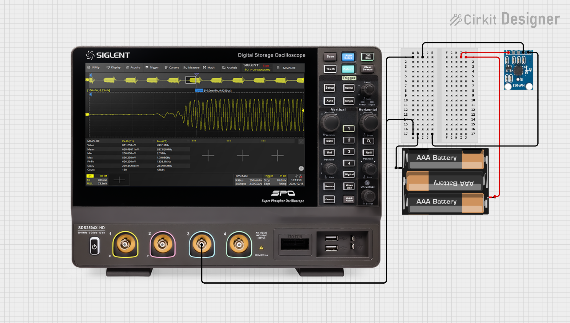 Open Project in Cirkit Designer
Explore Projects Built with Adafruit LIS3DH Triple-Axis Accelerometer
Open Project in Cirkit DesignerOpen Project in Cirkit DesignerOpen Project in Cirkit DesignerOpen Project in Cirkit DesignerCommon Applications
- Motion detection and gesture recognition
- Orientation sensing for mobile devices
- Tilt sensing in robotics and drones
- Step counting and activity tracking in wearables
- Vibration monitoring in industrial systems
Technical Specifications
The Adafruit LIS3DH accelerometer offers a range of features and specifications that make it suitable for a wide variety of applications.
Key Technical Details
| Parameter | Specification |
|---|---|
| Operating Voltage | 1.7V to 3.6V |
| Communication Interface | I2C (default) or SPI |
| Measurement Range | ±2g, ±4g, ±8g, ±16g (configurable) |
| Output Resolution | 16-bit |
| Data Rate | 1 Hz to 5.3 kHz |
| Operating Temperature | -40°C to +85°C |
| Dimensions | 2.0mm x 2.0mm x 1.0mm |
Pin Configuration and Descriptions
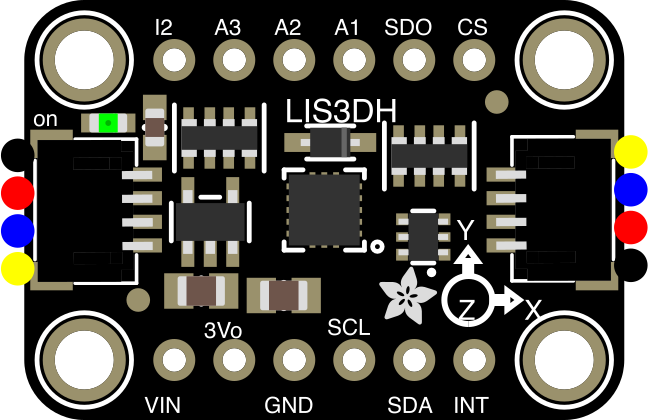
The LIS3DH breakout board from Adafruit includes the following pins:
| Pin Name | Description |
|---|---|
| VIN | Power input (3.3V or 5V). Regulated down to the sensor's operating voltage. |
| GND | Ground connection. |
| SCL | I2C clock line (or SPI clock line in SPI mode). |
| SDA | I2C data line (or SPI MOSI line in SPI mode). |
| SDO | I2C address selection (connect to GND for 0x18 or VIN for 0x19). |
| CS | Chip select for SPI mode (leave unconnected for I2C mode). |
| INT1 | Interrupt 1 output (configurable). |
| INT2 | Interrupt 2 output (configurable). |
Usage Instructions
The Adafruit LIS3DH can be used in either I2C or SPI mode, depending on your application. Below are the steps to integrate the sensor into your project.
Connecting the LIS3DH to an Arduino UNO (I2C Mode)
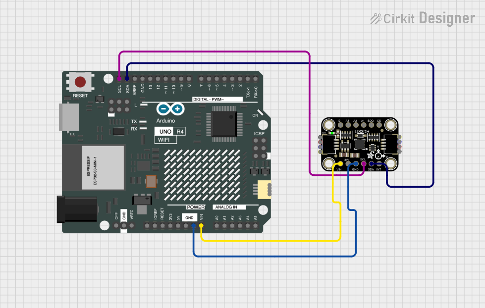
Wiring: Connect the LIS3DH breakout board to the Arduino UNO as follows:
VIN→5Von ArduinoGND→GNDon ArduinoSCL→A5on Arduino (I2C clock line)SDA→A4on Arduino (I2C data line)- Leave
CSunconnected for I2C mode. - Connect
SDOtoGNDfor I2C address0x18or toVINfor0x19.
Install the Adafruit LIS3DH Library:
- Open the Arduino IDE.
- Go to Sketch → Include Library → Manage Libraries.
- Search for "Adafruit LIS3DH" and install the library.
Example Code: Use the following example code to read acceleration data from the LIS3DH:
#include <Wire.h>
#include <Adafruit_LIS3DH.h>
#include <Adafruit_Sensor.h>

// Create an LIS3DH object using I2C
Adafruit_LIS3DH lis = Adafruit_LIS3DH();

void setup() {
  Serial.begin(9600);
  // Initialize the LIS3DH sensor
  if (!lis.begin(0x18)) { // 0x18 is the default I2C address
    Serial.println("Could not find a valid LIS3DH sensor, check wiring!");
    while (1); // Halt execution if sensor is not found
  }
  Serial.println("LIS3DH initialized!");

  // Set the range to ±2g (other options: ±4g, ±8g, ±16g)
  lis.setRange(LIS3DH_RANGE_2_G);
  Serial.println("Range set to ±2g");
}

void loop() {
  // Create a variable to store acceleration data
  sensors_event_t event;
  lis.getEvent(&event);

  // Print acceleration data to the Serial Monitor
  Serial.print("X: "); Serial.print(event.acceleration.x); Serial.print(" m/s^2 ");
  Serial.print("Y: "); Serial.print(event.acceleration.y); Serial.print(" m/s^2 ");
  Serial.print("Z: "); Serial.print(event.acceleration.z); Serial.println(" m/s^2");

  delay(500); // Wait 500ms before the next reading
}
Important Considerations
- Power Supply: Ensure the sensor is powered within its operating voltage range (1.7V to 3.6V). The breakout board includes a voltage regulator, so it can be powered with 3.3V or 5V.
- I2C Address: The default I2C address is
0x18. IfSDOis connected toVIN, the address changes to0x19. - Interrupts: The
INT1andINT2pins can be configured for various interrupt events, such as free-fall detection or activity recognition.
Troubleshooting and FAQs
Common Issues
Sensor Not Detected:
- Cause: Incorrect wiring or I2C address mismatch.
- Solution: Double-check the wiring and ensure the correct I2C address is used in the code.
No Data Output:
- Cause: The sensor is not initialized properly.
- Solution: Verify that the
lis.begin()function returnstrue. Check the power supply and connections.
Inaccurate Readings:
- Cause: Incorrect range setting or external vibrations.
- Solution: Set the appropriate range using
lis.setRange()and minimize external vibrations.
Interrupts Not Working:
- Cause: Interrupt pins not configured correctly.
- Solution: Refer to the Adafruit LIS3DH library documentation for interrupt configuration.
FAQs
Q: Can the LIS3DH be used with a 3.3V microcontroller?
A: Yes, the breakout board includes level-shifting circuitry, making it compatible with both 3.3V and 5V logic levels.
Q: How do I switch between I2C and SPI modes?
A: For I2C mode, leave the CS pin unconnected. For SPI mode, connect CS to a GPIO pin and configure the library accordingly.
Q: What is the maximum sampling rate of the LIS3DH?
A: The LIS3DH supports data rates up to 5.3 kHz, but higher rates may increase power consumption.
Q: Can the LIS3DH detect free-fall events?
A: Yes, the LIS3DH includes built-in free-fall detection, which can be configured using the interrupt pins.
By following this documentation, you can effectively integrate the Adafruit LIS3DH accelerometer into your projects and troubleshoot common issues.