How to Use JSY-MK-1039: Examples, Pinouts, and Specs
Introduction
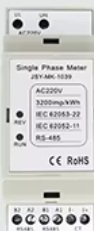
The JSY-MK-1039 is a compact, low-profile tactile switch designed for user input in electronic devices. It features a reliable mechanical action and is available in a variety of actuation forces to suit different applications. This switch is widely used in consumer electronics, industrial control panels, and prototyping projects due to its durability and ease of integration.
Explore Projects Built with JSY-MK-1039
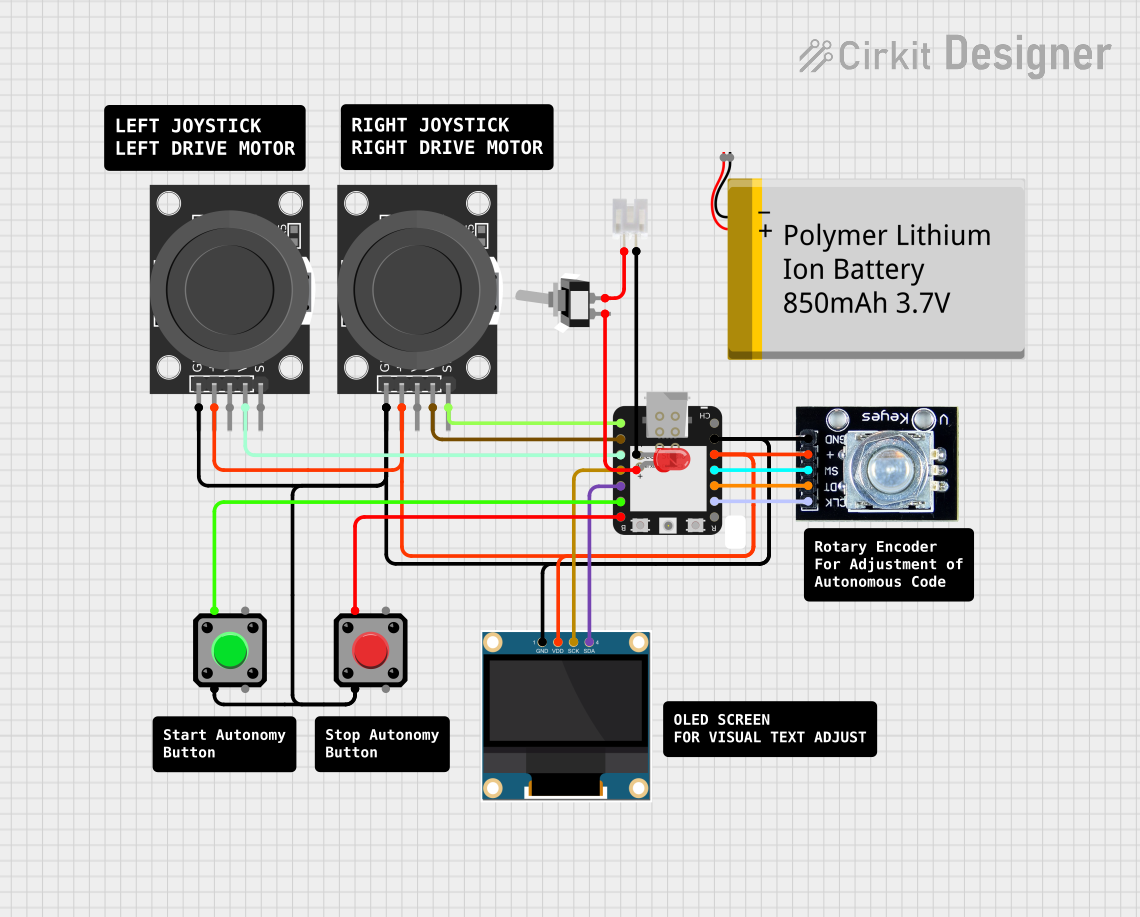
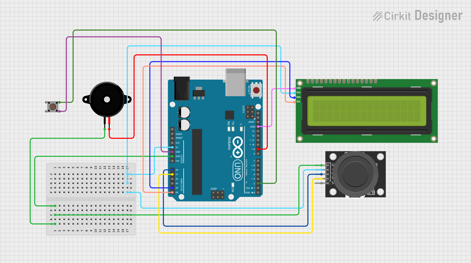
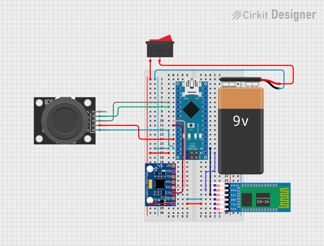

Explore Projects Built with JSY-MK-1039
Common Applications
- Keyboards and keypads
- Remote controls
- Consumer electronics (e.g., calculators, gaming devices)
- Industrial control systems
- DIY electronics and prototyping
Technical Specifications
Key Specifications
| Parameter | Value |
|---|---|
| Operating Voltage | 12V DC (maximum) |
| Operating Current | 50mA (maximum) |
| Contact Resistance | ≤ 100mΩ |
| Insulation Resistance | ≥ 100MΩ at 500V DC |
| Actuation Force | 100g, 160g, or 260g (varies by model) |
| Travel Distance | 0.25mm ± 0.1mm |
| Operating Temperature | -25°C to +70°C |
| Mechanical Lifespan | 100,000 cycles (minimum) |
Pin Configuration and Descriptions
The JSY-MK-1039 is a 4-pin tactile switch. The pins are arranged in a square configuration, with two pairs of pins internally connected. Below is the pinout description:
| Pin Number | Description |
|---|---|
| 1 | Connected to one side of the switch |
| 2 | Connected to the same side as Pin 1 |
| 3 | Connected to the opposite side of the switch |
| 4 | Connected to the same side as Pin 3 |
Note: Pins 1 and 2 are internally connected, as are Pins 3 and 4. This allows for easy integration into circuits regardless of orientation.
Usage Instructions
How to Use the JSY-MK-1039 in a Circuit
- Placement on PCB: The JSY-MK-1039 is designed for through-hole mounting. Insert the pins into the PCB and solder them securely.
- Connection: Connect one pair of pins (e.g., Pins 1 and 2) to the input signal or power source. Connect the other pair (Pins 3 and 4) to the output or ground, depending on the circuit design.
- Debouncing: Tactile switches can produce noise or "bouncing" when pressed. Use a debouncing circuit or software algorithm to ensure stable operation.
- Pull-Up or Pull-Down Resistor: When interfacing with a microcontroller, use a pull-up or pull-down resistor to maintain a defined logic state when the switch is not pressed.
Example: Connecting to an Arduino UNO
The JSY-MK-1039 can be easily connected to an Arduino UNO for user input. Below is an example circuit and code:
Circuit Diagram
- Connect one side of the switch (Pins 1 and 2) to a digital input pin on the Arduino (e.g., Pin 2).
- Connect the other side of the switch (Pins 3 and 4) to ground.
- Use the Arduino's internal pull-up resistor to simplify the circuit.
Arduino Code
// Example code for using the JSY-MK-1039 with an Arduino UNO
const int buttonPin = 2;  // Pin connected to the JSY-MK-1039
int buttonState = 0;      // Variable to store the button state

void setup() {
  pinMode(buttonPin, INPUT_PULLUP); // Set pin as input with internal pull-up resistor
  Serial.begin(9600);              // Initialize serial communication
}

void loop() {
  buttonState = digitalRead(buttonPin); // Read the state of the button

  if (buttonState == LOW) {
    // Button is pressed (LOW because of pull-up resistor)
    Serial.println("Button Pressed");
  } else {
    // Button is not pressed
    Serial.println("Button Released");
  }

  delay(100); // Small delay to avoid excessive serial output
}
Important Considerations
- Voltage and Current Limits: Do not exceed the maximum operating voltage (12V DC) or current (50mA) to avoid damaging the switch.
- Debouncing: Always implement debouncing to ensure reliable operation in digital circuits.
- Mechanical Stress: Avoid applying excessive force to the switch to maintain its mechanical lifespan.
Troubleshooting and FAQs
Common Issues and Solutions
Switch Not Responding:
- Cause: Poor soldering or loose connections.
- Solution: Check and re-solder the connections. Ensure the switch is properly seated on the PCB.
Unstable or Erratic Behavior:
- Cause: Switch bouncing or lack of debouncing.
- Solution: Add a hardware debouncing circuit (e.g., capacitor) or implement software debouncing in your code.
Switch Feels Stiff or Unresponsive:
- Cause: Dirt or debris inside the switch.
- Solution: Clean the switch gently with compressed air. If the issue persists, replace the switch.
Exceeding Voltage/Current Ratings:
- Cause: Using the switch in a high-power circuit.
- Solution: Ensure the circuit operates within the switch's voltage and current limits. Use a relay or transistor for high-power applications.
FAQs
Q: Can the JSY-MK-1039 be used in high-power circuits?
A: No, the JSY-MK-1039 is designed for low-power applications. For high-power circuits, use a relay or transistor to handle the load.
Q: How do I choose the right actuation force?
A: The choice depends on the application. For light-touch applications, use the 100g model. For more tactile feedback, choose the 160g or 260g models.
Q: Is the JSY-MK-1039 waterproof?
A: No, the JSY-MK-1039 is not waterproof. Use it in dry environments or consider a sealed switch for outdoor applications.
Q: Can I use the JSY-MK-1039 with a Raspberry Pi?
A: Yes, the JSY-MK-1039 can be used with a Raspberry Pi. Connect it to a GPIO pin and use a pull-up or pull-down resistor as needed.
This concludes the documentation for the JSY-MK-1039 tactile switch.