
How to Use Sony's Spresense Extension Board: Examples, Pinouts, and Specs

 Design with Sony's Spresense Extension Board in Cirkit Designer
Introduction
The Sony Spresense Extension Board (CXD5602PWBEXT1) is a versatile expansion board designed to complement the Sony Spresense microcontroller. It provides additional interfaces and connectivity options, such as GPIO, I2C, SPI, UART, and audio input/output, enabling developers to create advanced IoT and embedded applications. This board is ideal for projects requiring enhanced functionality, such as environmental monitoring, robotics, audio processing, and wearable devices.
Explore Projects Built with Sony's Spresense Extension Board
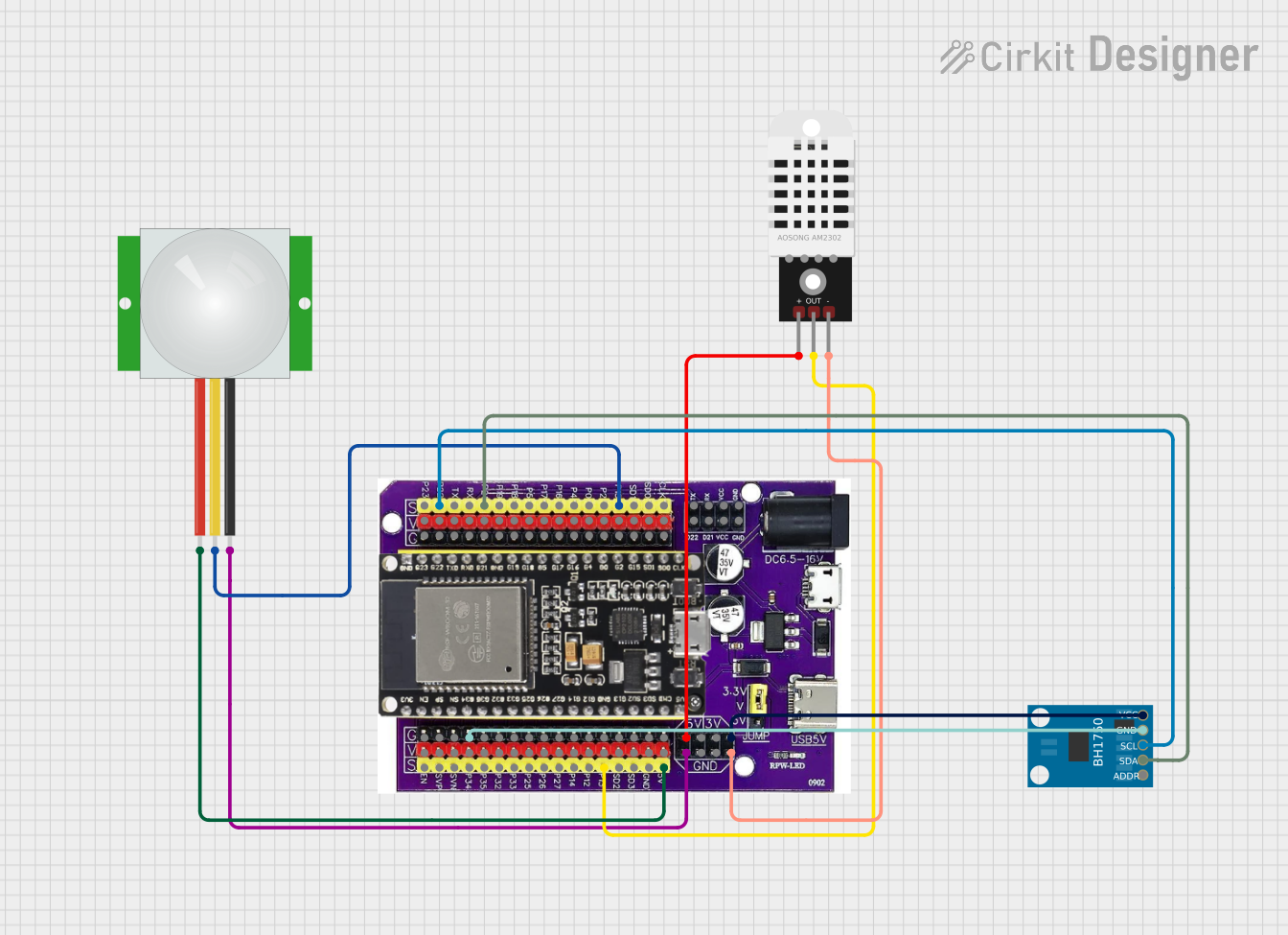 Open Project in Cirkit Designer
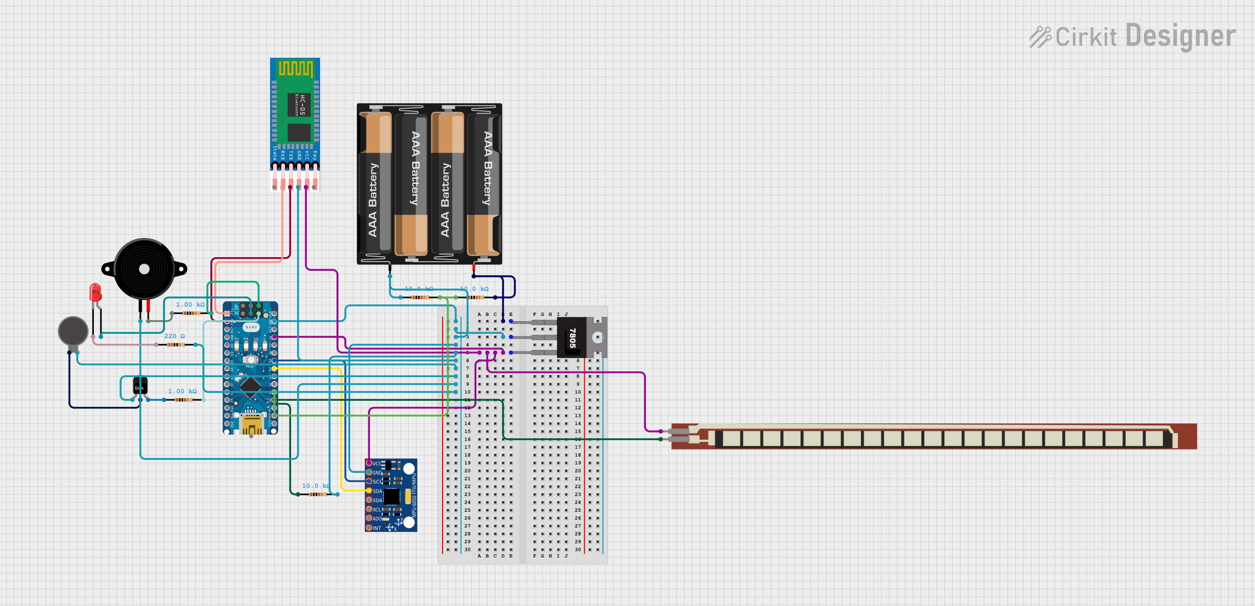 Open Project in Cirkit Designer
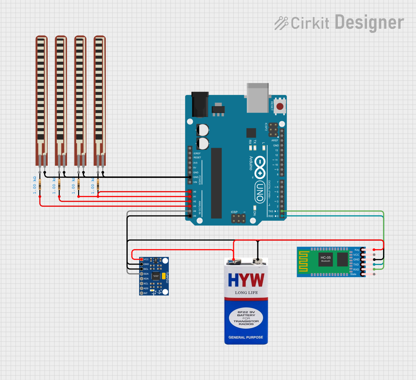 Open Project in Cirkit Designer
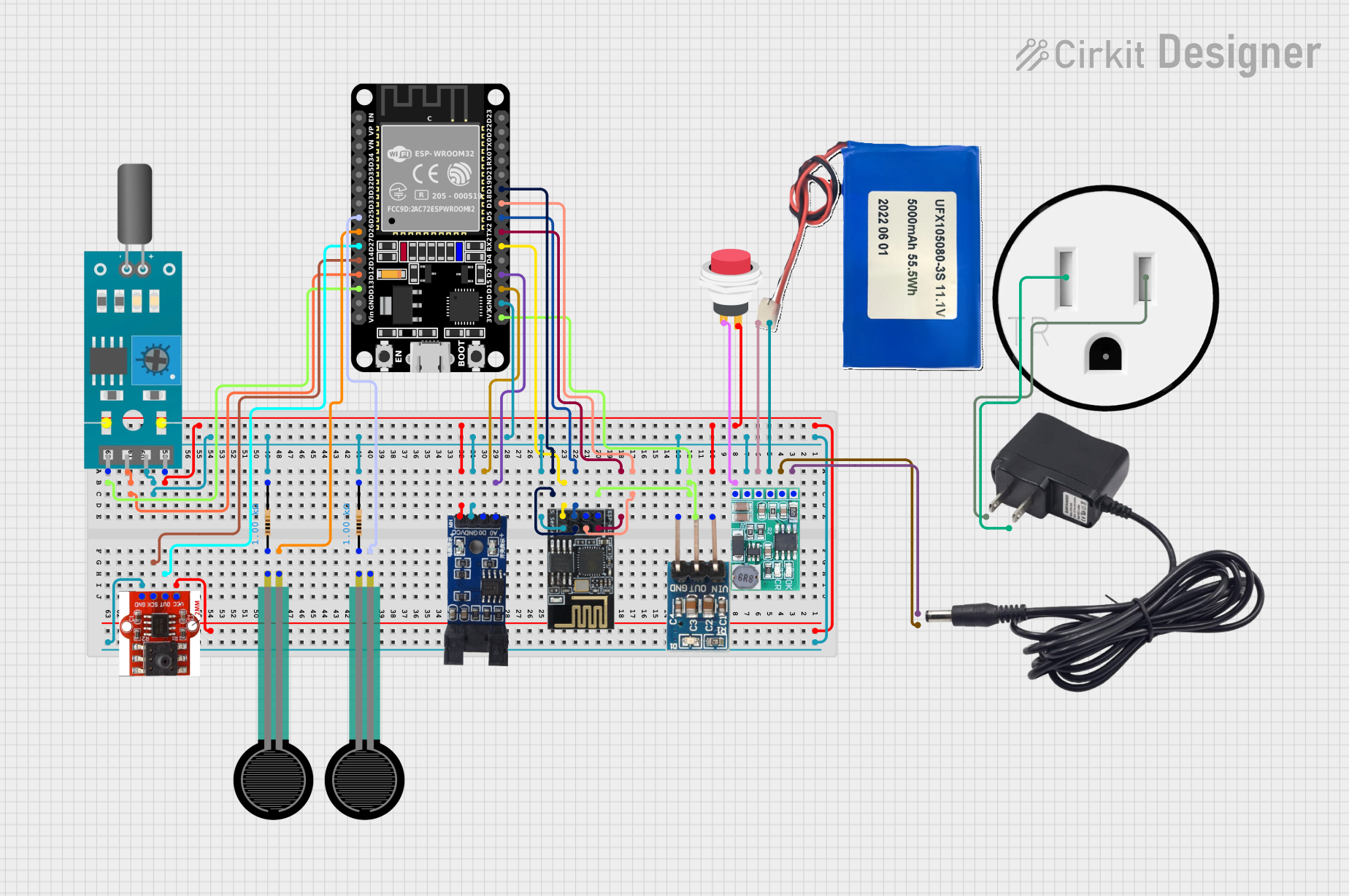 Open Project in Cirkit Designer
Explore Projects Built with Sony's Spresense Extension Board
Open Project in Cirkit DesignerOpen Project in Cirkit DesignerOpen Project in Cirkit DesignerOpen Project in Cirkit DesignerCommon Applications
- IoT devices and smart home systems
- Robotics and automation
- Audio processing and recording
- Environmental monitoring and data logging
- Prototyping and development of embedded systems
Technical Specifications
Key Technical Details
| Parameter | Specification |
|---|---|
| Manufacturer | Sony |
| Part Number | CXD5602PWBEXT1 |
| Compatible Microcontroller | Sony Spresense Main Board (CXD5602) |
| Power Supply Voltage | 5V (via USB or external power supply) |
| Interfaces | GPIO, I2C, SPI, UART, PWM, ADC, DAC, SD card slot, and audio input/output |
| Audio Features | Stereo headphone jack, microphone input, and speaker output |
| Dimensions | 68.6 mm x 31.8 mm |
| Operating Temperature Range | -20°C to +85°C |
Pin Configuration and Descriptions
The Sony Spresense Extension Board provides a variety of pins for interfacing with external components. Below is the pin configuration:
GPIO and Communication Pins
| Pin Name | Type | Description |
|---|---|---|
| GPIO0-GPIO13 | Digital I/O | General-purpose input/output pins for digital signals |
| I2C_SCL | I2C Clock | Clock line for I2C communication |
| I2C_SDA | I2C Data | Data line for I2C communication |
| SPI_MOSI | SPI Data Out | Master Out Slave In (MOSI) for SPI communication |
| SPI_MISO | SPI Data In | Master In Slave Out (MISO) for SPI communication |
| SPI_SCK | SPI Clock | Clock line for SPI communication |
| UART_TX | UART Transmit | Transmit line for UART communication |
| UART_RX | UART Receive | Receive line for UART communication |
Power and Audio Pins
| Pin Name | Type | Description |
|---|---|---|
| VIN | Power Input | External power input (5V) |
| GND | Ground | Ground connection |
| HP_OUT_L | Audio Output | Left channel for stereo headphone output |
| HP_OUT_R | Audio Output | Right channel for stereo headphone output |
| MIC_IN | Audio Input | Microphone input for audio recording |
| SPK_OUT | Audio Output | Speaker output for external speakers |
Usage Instructions
How to Use the Component in a Circuit
- Connect the Extension Board to the Main Board: Align the pins of the Sony Spresense Main Board with the connectors on the Extension Board and press them together gently.
- Power the Board: Supply power to the board via the USB connector or an external 5V power source.
- Connect Peripherals: Use the GPIO, I2C, SPI, or UART pins to connect sensors, actuators, or other peripherals. For audio applications, connect headphones, microphones, or speakers to the respective audio jacks.
- Program the Main Board: Write and upload your code to the Sony Spresense Main Board using the Arduino IDE or Sony's Spresense SDK.
Important Considerations and Best Practices
- Ensure that the power supply voltage does not exceed the specified range (5V) to avoid damaging the board.
- Use appropriate pull-up resistors for I2C communication if required by your peripherals.
- When using audio features, ensure that the connected devices (e.g., headphones or speakers) match the board's output specifications.
- Avoid shorting the GPIO pins or connecting them to voltages beyond their rated limits.
Example Code for Arduino UNO
Below is an example of how to use the I2C interface on the Sony Spresense Extension Board to communicate with a sensor:
#include <Wire.h> // Include the Wire library for I2C communication

#define SENSOR_ADDRESS 0x40 // Replace with your sensor's I2C address

void setup() {
  Wire.begin(); // Initialize I2C communication
  Serial.begin(9600); // Start serial communication for debugging
  Serial.println("I2C Communication Initialized");
}

void loop() {
  Wire.beginTransmission(SENSOR_ADDRESS); // Start communication with the sensor
  Wire.write(0x00); // Send a command to the sensor (e.g., read temperature)
  Wire.endTransmission(); // End the transmission

  Wire.requestFrom(SENSOR_ADDRESS, 2); // Request 2 bytes of data from the sensor
  if (Wire.available() == 2) { // Check if 2 bytes are available
    int data = Wire.read() << 8 | Wire.read(); // Read and combine the data
    Serial.print("Sensor Data: ");
    Serial.println(data); // Print the sensor data
  }

  delay(1000); // Wait for 1 second before the next reading
}
Troubleshooting and FAQs
Common Issues and Solutions
The board does not power on:
- Ensure that the USB cable or external power supply is properly connected.
- Verify that the power supply voltage is 5V.
Peripherals are not responding:
- Check the wiring and connections to ensure they are correct.
- Verify that the correct pins are being used for communication (e.g., I2C, SPI, or UART).
- Ensure that the peripheral device is powered and functioning.
Audio output is distorted or not working:
- Verify that the connected headphones or speakers are compatible with the board.
- Check the audio connections for loose or incorrect wiring.
Unable to upload code to the main board:
- Ensure that the Sony Spresense Main Board is properly connected to the Extension Board.
- Verify that the correct board and port are selected in the Arduino IDE or Spresense SDK.
FAQs
Q: Can I use the Extension Board without the Main Board?
A: No, the Extension Board is designed to work in conjunction with the Sony Spresense Main Board and cannot function independently.
Q: What is the maximum current output of the GPIO pins?
A: The GPIO pins can source or sink up to 4mA per pin. Ensure not to exceed this limit to avoid damage.
Q: Can I use the Extension Board for battery-powered applications?
A: Yes, the board supports external power input, which can be supplied by a battery pack. Ensure the voltage is regulated to 5V.
Q: Is the Extension Board compatible with other microcontrollers?
A: The Extension Board is specifically designed for the Sony Spresense Main Board and may not be compatible with other microcontrollers.