How to Use Microstep Driver : Examples, Pinouts, and Specs
Introduction
A microstep driver is an electronic device designed to control the movement of stepper motors with high precision. By dividing each full step of the motor into smaller increments, the microstep driver enables smoother and more accurate motion. This makes it an essential component in applications requiring precise positioning and reduced vibration.
Explore Projects Built with Microstep Driver

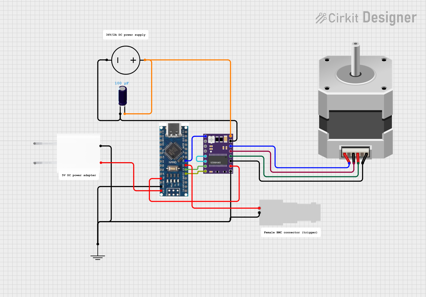
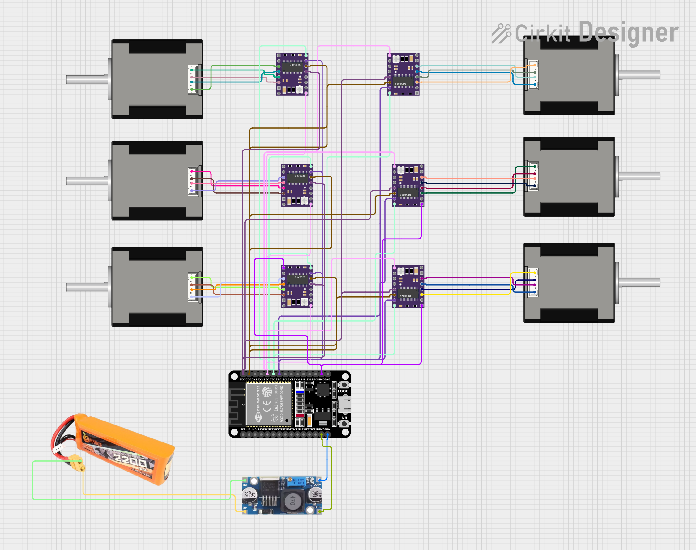
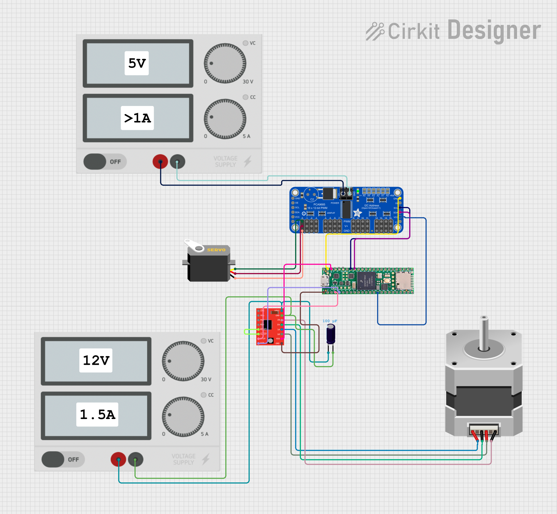
Explore Projects Built with Microstep Driver
Common Applications and Use Cases
- CNC machines and 3D printers
- Robotics and automation systems
- Camera gimbals and pan-tilt mechanisms
- Medical devices requiring precise motion control
- Laser cutters and engraving machines
Technical Specifications
Below are the general technical specifications for a typical microstep driver. Always refer to the datasheet of your specific model for exact details.
Key Technical Details
- Input Voltage Range: 12V to 48V DC (varies by model)
- Output Current: 0.5A to 5.6A (adjustable)
- Microstepping Resolution: 1, 2, 4, 8, 16, 32, or higher (model-dependent)
- Control Signal Voltage: 3.3V or 5V logic compatible
- Step Frequency: Up to 200 kHz
- Operating Temperature: -10°C to 50°C
- Protection Features: Over-voltage, under-voltage, over-current, and short-circuit protection
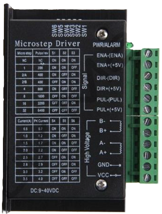
Pin Configuration and Descriptions
The pinout of a microstep driver typically includes power, motor, and control signal connections. Below is a general example:
| Pin Name | Description |
|---|---|
| V+ | Positive power supply input (e.g., 12V to 48V DC). |
| GND | Ground connection for the power supply. |
| A+ / A- | Outputs for connecting to one phase of the stepper motor. |
| B+ / B- | Outputs for connecting to the other phase of the stepper motor. |
| PUL+ / PUL- | Pulse signal input for controlling the stepper motor's steps. |
| DIR+ / DIR- | Direction signal input to control the rotation direction of the motor. |
| ENA+ / ENA- | Enable signal input to activate or deactivate the driver (optional). |
Note: Some microstep drivers may combine PUL+, DIR+, and ENA+ into a single common pin.
Usage Instructions
How to Use the Microstep Driver in a Circuit
- Power Supply: Connect the V+ and GND pins to a DC power supply within the specified voltage range.
- Motor Connection: Connect the stepper motor's two coils to the A+/A- and B+/B- outputs. Ensure the wiring matches the motor's datasheet.
- Control Signals:
- Connect the PUL+, DIR+, and ENA+ pins to the control signals from a microcontroller (e.g., Arduino).
- Use appropriate resistors or level shifters if the microcontroller's logic voltage differs from the driver's input requirements.
- Microstepping Configuration: Set the microstepping resolution using DIP switches or jumpers on the driver (if available).
- Testing: Power on the system and send pulse and direction signals to the driver to test motor movement.
Important Considerations and Best Practices
- Current Adjustment: Set the output current limit on the driver to match the stepper motor's rated current. This prevents overheating and damage.
- Cooling: Ensure proper ventilation or heat sinking for the driver, especially in high-current applications.
- Signal Quality: Use shielded cables for control signals to minimize noise interference.
- Power Supply: Use a stable and adequately rated power supply to avoid voltage drops or surges.
Example: Connecting to an Arduino UNO
Below is an example Arduino sketch to control a stepper motor using a microstep driver.
// Define pin connections for the microstep driver
const int stepPin = 3;  // Pin connected to PUL+ (Pulse)
const int dirPin = 4;   // Pin connected to DIR+ (Direction)

void setup() {
  pinMode(stepPin, OUTPUT); // Set step pin as output
  pinMode(dirPin, OUTPUT);  // Set direction pin as output

  digitalWrite(dirPin, HIGH); // Set initial direction (HIGH = clockwise)
}

void loop() {
  // Generate pulses to move the stepper motor
  digitalWrite(stepPin, HIGH); // Set step pin HIGH
  delayMicroseconds(500);      // Wait for 500 microseconds
  digitalWrite(stepPin, LOW);  // Set step pin LOW
  delayMicroseconds(500);      // Wait for 500 microseconds

  // Repeat to create continuous motion
}
Note: Adjust the
delayMicroseconds()values to control the motor's speed. A shorter delay results in faster motion.
Troubleshooting and FAQs
Common Issues and Solutions
Motor Not Moving:
- Verify all connections, especially the motor coils and control signals.
- Check the power supply voltage and current rating.
- Ensure the microcontroller is sending pulses to the PUL+ pin.
Motor Vibrates but Doesn't Rotate:
- Check the wiring of the motor coils. Incorrect wiring can cause improper operation.
- Verify the microstepping configuration and adjust if necessary.
Driver Overheating:
- Ensure the current limit is set correctly for the motor.
- Improve cooling with a heat sink or fan.
Inconsistent Motor Movement:
- Check for noise or interference in the control signal lines.
- Use shielded cables and proper grounding.
FAQs
Q: Can I use a microstep driver with any stepper motor?
A: Microstep drivers are compatible with most bipolar stepper motors. Ensure the motor's voltage and current ratings match the driver's specifications.
Q: How do I choose the microstepping resolution?
A: Higher resolutions provide smoother motion but may reduce torque. Choose a resolution based on your application's precision and torque requirements.
Q: What happens if I exceed the driver's voltage or current limits?
A: Exceeding the limits can damage the driver or motor. Always operate within the specified range and use a properly rated power supply.
Q: Can I control multiple drivers with one microcontroller?
A: Yes, as long as the microcontroller has enough GPIO pins and processing power to handle multiple pulse and direction signals.
By following this documentation, you can effectively use a microstep driver to achieve precise and reliable stepper motor control.