
How to Use USB FIFO Controller: Examples, Pinouts, and Specs
 Design with USB FIFO Controller in Cirkit Designer
Introduction
The FT245RL, manufactured by FTDI Chip, is a USB FIFO (First In, First Out) Controller designed to facilitate seamless data transfer between USB devices and a host system. It acts as a bridge, managing data flow efficiently by temporarily storing data in a queue. This component is widely used in applications requiring USB connectivity, such as embedded systems, data acquisition, and USB-to-parallel interfaces.
Explore Projects Built with USB FIFO Controller
 Open Project in Cirkit Designer
 Open Project in Cirkit Designer
 Open Project in Cirkit Designer
 Open Project in Cirkit Designer
Explore Projects Built with USB FIFO Controller
Open Project in Cirkit DesignerOpen Project in Cirkit DesignerOpen Project in Cirkit DesignerOpen Project in Cirkit DesignerCommon Applications and Use Cases
- USB-to-parallel data transfer
- Embedded systems requiring USB communication
- Data acquisition systems
- USB-based debugging tools
- Industrial automation and control systems
Technical Specifications
The FT245RL is a high-performance USB FIFO controller with the following key specifications:
Key Technical Details
| Parameter | Value |
|---|---|
| USB Standard | USB 2.0 Full-Speed (12 Mbps) |
| FIFO Data Bus Width | 8-bit |
| Operating Voltage | 3.3V (core) / 5V (I/O) |
| Current Consumption | 15 mA (typical) |
| Data Transfer Rate | Up to 1 MB/s |
| EEPROM | Integrated 1024-bit EEPROM |
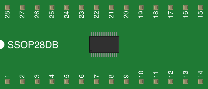
| Package | SSOP-28 |
| Operating Temperature | -40°C to +85°C |
Pin Configuration and Descriptions
The FT245RL comes in a 28-pin SSOP package. Below is the pin configuration:
| Pin No. | Name | Type | Description |
|---|---|---|---|
| 1 | TXE# | Output | Indicates when the FIFO is empty (active low). |
| 2 | RXF# | Output | Indicates when data is available in the FIFO (active low). |
| 3 | RD# | Input | Read strobe signal to read data from the FIFO. |
| 4 | WR | Input | Write strobe signal to write data to the FIFO. |
| 5 | D0 | I/O | Data bus bit 0. |
| 6 | D1 | I/O | Data bus bit 1. |
| 7 | D2 | I/O | Data bus bit 2. |
| 8 | D3 | I/O | Data bus bit 3. |
| 9 | D4 | I/O | Data bus bit 4. |
| 10 | D5 | I/O | Data bus bit 5. |
| 11 | D6 | I/O | Data bus bit 6. |
| 12 | D7 | I/O | Data bus bit 7. |
| 13 | VCCIO | Power | I/O voltage supply (3.3V or 5V). |
| 14 | GND | Ground | Ground reference. |
| 15 | VCC | Power | Core voltage supply (3.3V). |
| 16 | RESET# | Input | Active low reset input. |
| 17 | TEST | Input | Test pin (must be tied to GND for normal operation). |
| 18 | EECS | I/O | EEPROM chip select (used for external EEPROM programming). |
| 19 | EESK | Output | EEPROM clock signal. |
| 20 | EEDATA | I/O | EEPROM data signal. |
| 21 | USBDP | I/O | USB D+ line. |
| 22 | USBDM | I/O | USB D- line. |
| 23 | VCCPLL | Power | PLL voltage supply (3.3V). |
| 24 | GNDPLL | Ground | PLL ground reference. |
| 25 | PWREN# | Output | Power enable signal (active low). |
| 26 | SLEEP# | Output | Indicates USB suspend mode (active low). |
| 27 | CLKOUT | Output | 12 MHz clock output. |
| 28 | NC | - | No connection. |
Usage Instructions
How to Use the FT245RL in a Circuit
- Power Supply: Connect the VCC pin to a 3.3V power source and the VCCIO pin to either 3.3V or 5V, depending on the desired I/O voltage level. Ensure all GND pins are connected to the ground plane.
- USB Connection: Connect the USBDP and USBDM pins to the USB D+ and D- lines, respectively. Use a USB connector for interfacing with the host system.
- FIFO Interface: Use the D0-D7 pins for data transfer. Control the data flow using the RD#, WR, RXF#, and TXE# pins.
- EEPROM Configuration: The integrated EEPROM can be programmed to customize USB descriptors, such as Vendor ID (VID), Product ID (PID), and device strings.
- Clock Output: The CLKOUT pin provides a 12 MHz clock signal, which can be used to synchronize external components.
Important Considerations and Best Practices
- Pull-Up Resistors: Ensure proper pull-up resistors are used on the USB D+ line for USB compliance.
- Decoupling Capacitors: Place decoupling capacitors (e.g., 0.1 µF) close to the VCC and VCCIO pins to reduce noise.
- EEPROM Programming: Use FTDI's FT_PROG utility to program the integrated EEPROM.
- Reset Pin: Tie the RESET# pin to VCC through a pull-up resistor if not used.
- Thermal Management: Ensure adequate ventilation or heat dissipation for reliable operation in high-temperature environments.
Example: Connecting FT245RL to an Arduino UNO
The FT245RL can be used to interface an Arduino UNO with a USB host. Below is an example Arduino sketch to read data from the FT245RL:
// Example code to read data from FT245RL using Arduino UNO
#define RXF 2  // Pin 2 connected to RXF# of FT245RL
#define RD  3  // Pin 3 connected to RD# of FT245RL
#define D0  4  // Pin 4 connected to D0 of FT245RL
#define D1  5  // Pin 5 connected to D1 of FT245RL
#define D2  6  // Pin 6 connected to D2 of FT245RL
#define D3  7  // Pin 7 connected to D3 of FT245RL

void setup() {
  pinMode(RXF, INPUT);  // RXF# is an input signal
  pinMode(RD, OUTPUT);  // RD# is an output signal
  pinMode(D0, INPUT);   // Data bus pins are inputs
  pinMode(D1, INPUT);
  pinMode(D2, INPUT);
  pinMode(D3, INPUT);
  Serial.begin(9600);   // Initialize serial communication
}

void loop() {
  if (digitalRead(RXF) == LOW) {  // Check if data is available
    digitalWrite(RD, LOW);        // Assert RD# to read data
    delayMicroseconds(1);         // Small delay for data setup
    int data = (digitalRead(D3) << 3) | (digitalRead(D2) << 2) |
               (digitalRead(D1) << 1) | digitalRead(D0);  // Read 4-bit data
    digitalWrite(RD, HIGH);       // De-assert RD#
    Serial.println(data, HEX);    // Print data in hexadecimal format
  }
}
Troubleshooting and FAQs
Common Issues and Solutions
Device Not Recognized by Host
- Ensure the USB D+ and D- lines are correctly connected.
- Verify that the pull-up resistor on the D+ line is properly installed.
- Check the USB cable and connector for damage.
No Data Transfer
- Confirm that the RXF# and TXE# signals are being monitored correctly.
- Verify that the RD# and WR signals are being toggled as required.
- Ensure the FIFO data bus (D0-D7) is correctly connected.
EEPROM Programming Fails
- Ensure the FT_PROG utility is installed and configured correctly.
- Verify that the EECS, EESK, and EEDATA pins are properly connected.
FAQs
Can the FT245RL operate at 5V?
- Yes, the FT245RL supports 5V operation for its I/O pins when VCCIO is set to 5V. However, the core voltage (VCC) must always be 3.3V.
What is the maximum data transfer rate?
- The FT245RL supports data transfer rates of up to 1 MB/s.
**Is an external crystal required?